Asset movement recognition
Introduction
This tutorial guides you through the development and testing of an Asset Movement Recognition (AMR) application using the Renesas AIK-RA6M3 Solution Kit and the Reality AI Tools portal. The goal is to build a foundational AMR project from scratch and integrate it with HAL drivers provided by the Flexible Software Package (FSP).
You will gain practical experience in creating a non-visual sensing AI application that detects motion using accelerometer data. The trained model will run on edge hardware and display real-time inference outputs using the AIK-RA6M3 kit.
Objectives
By the end of this tutorial, you will be able to:
- Set up and configure the Renesas AIK-RA6M3 Solution Kit.
- Use Reality AI Tools to generate an AI model for motion recognition.
- Import the model into e² Studio and run the demo application on hardware.
- Observe real-time inference output for movement detection using the PMOD accelerometer.
Prerequisites
Hardware
Ensure the following components are available:
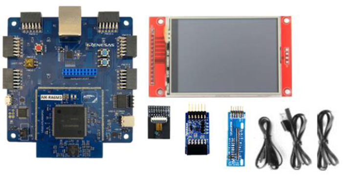
- AIK-RA6M3 kit, which includes:
- AIK-RA6M3 board
- OV2640 camera module
- Renesas ICM-42670P PMOD accelerometer board
- Display module
- Ethernet patch cable
- Micro USB cable (Type-A to Micro-B)
- USB cable (Type-A to Type-C)
- PC (Windows 10 or later)
Software
-
e² Studio IDE version 2024-07 or later
-
Flexible Software Package (FSP) version 5.5.0 or later
Note: This guide was tested with e² Studio 2024-07 and FSP 5.5. If using a newer version, additional configuration steps may be required.
-
Reality AI Tools account
Access the portal at: https://portal.reality.ai/login
Credentials should be provided by the Renesas – Reality AI team. Contact them if you do not have access. -
Demo project files provided by the Reality AI team (download link in Section 1 of this document)
Dataset
This lab uses Sample dataset from the PMOD accelerometer (ICM-42670P) captured using the Reality AI Monitor. These datasets will be used to train, validate, and test the asset movement recognition model in the Reality AI Tools portal.
Estimated Completion Time
2 to 3 hours, depending on familiarity with:
- Embedded system hardware setup
- Using e² Studio and FSP configuration
- Navigating the Reality AI Tools portal
Step-by-Step Instructions
Step 1: Experimental Setup
Step 1.1: Hardware Setup
- Use the AIK-RA6M3 and Renesas ICM-42670P PMOD accelerometer.
- Connect the PMOD board to the PMOD 1 connector on the main board.
- Set the S4 DIP switch to IIC mode.
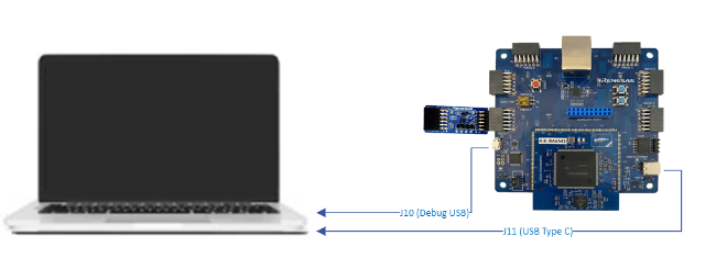
- Connect the PC to the board using the Micro USB and USB Type-C cables.
Step 1.2: Software Setup
- Install e² Studio IDE 2024-07 or later.
This tutorial requires Renesas e² Studio IDE version 2024-07 or later, with Flexible Software Package (FSP) version 5.5.0 or later. The instructions in this document are validated against e² Studio 2024-07 and FSP 5.5.0. If you are using a newer version, additional configuration steps may be required.
You can download the platform installer from the following link: Click to download
Make a note of the installation directory for e² Studio, as it will be referenced later in this tutorial.
- Create or log in to your Reality AI Tools account.
- Open https://portal.reality.ai/login in a web browser.
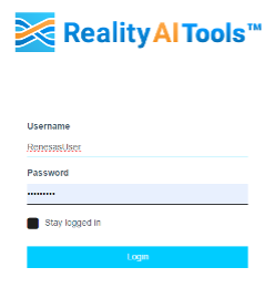
- Use your assigned credentials.
- Leave the portal open for further use.
Step 2: Enable the Accelerometer
This section describes how to configure an accelerometer demo project for the AIK-RA6M3 kit using e² Studio and the Flexible Software Package (FSP).
Step 2.1: Launch e² Studio
- Launch e² Studio from the Windows Start menu or directly from the installation directory.
- If multiple versions of e² Studio are installed, launch the version that matches the installed FSP for this project.
- Refer to the FSP migration guide in the
renesas/aiot-readyrepository to switch between FSP versions and minimize compatibility issues.
Step 2.2: Set Workspace Location
- In the Eclipse Launcher window, specify a workspace directory.
- Use a simple path with no spaces.
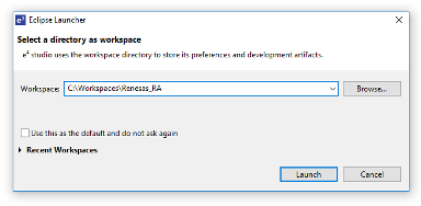
- Click Launch.
- If prompted about usage logging, click Apply to dismiss.
- Click Hide in the top-right corner of the welcome screen.

Step 2.3: Create a New RA Project
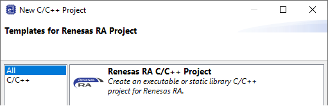
- Navigate to File > New > Renesas C/C++ Project > Renesas RA.
- In the new project wizard:
- Select Renesas RA C/C++ Project, then click Next.
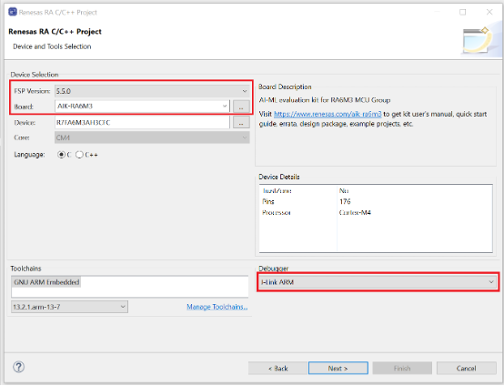
- Specify a project name.
- Select the FSP version (e.g., 5.5.0) and set the board to AIK-RA6M3.
- Ensure the Debugger is set to J-Link ARM, then click Next.
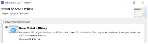
- Select Executable and No RTOS, then click Next.
- Choose Bare Metal – Blinky and click Finish.
Step 2.4: Open FSP Configuration Perspective
- Open the FSP Configuration Perspective, and when prompted, click Open Perspective. The project is now ready for evaluation and development using the AIK.
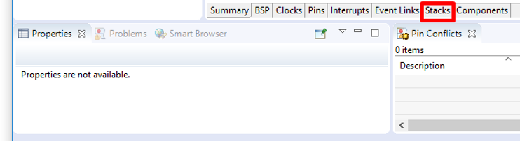
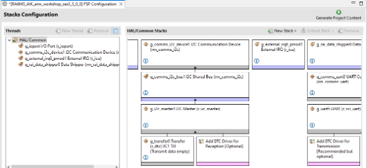
- Once the new project is created, e² Studio automatically switches to a layout optimized for developing Renesas RA projects. Select the Stacks tab at the bottom of the FSP Configuration view.
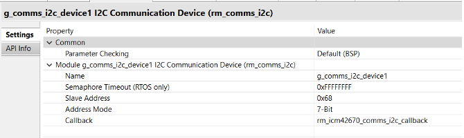
Step 2.5: Add I2C Communication Device (rm_comms_i2c)
- Navigate to New Stack > Connectivity > I2C Communication Device (rm_comms_i2c).
- Set the following in the Properties tab:
- Name:
g_comms_i2c_device1 - Slave Address:
0x68 - Callback:
rm_icm42670_comms_i2c_callback
- Name:
Step 2.6: Configure I2C Shared Bus
- Under
g_comms_i2c_bus1 (rm_comms_i2c), on the Properties tab, configure the following properties for this new module:- Name:
g_comms_i2c_bus1 - Channel:
1 - Rate:
Fast-mode
- Name:
Step 2.7: Add I2C Master (r_iic_master)
- Click Add I2C Communications peripherals > New > I2C Master (r_iic_master).
- On the Properties tab, set:
- DTC on Transmission and Reception:
Enabled - Name:
g_i2c_master1 - Interrupt Priority:
12 - Timeout Mode:
Short Mode
- DTC on Transmission and Reception:
Step 2.8: Add DTC Driver for Transmission (optional)
Click the stack icon for Add DTC Driver for Transmission > New > Transfer (r_dtc).
Step 2.9: Add External IRQ (r_icu)
- Navigate to New Stack > Input > External IRQ (r_icu).
- On the Properties tab, set:
- Name:
g_external_irq6_pmod1 - Channel:
6 - Trigger:
Rising - Interrupt Priority:
Priority 12
- Name:
Note: When you change Channel to 6, pin IRQ06 should map to
P000.
Step 2.10: Add Data Shipper (rm_rai_data_shipper)
- Navigate to New Stack > AI > Data Shipper (rm_rai_data_shipper).
Step 2.11: Configure Data Collector
- Under
g_rai_data_collector0, on the Properties tab, set:- General > Frame Buffer Length:
512 - Data Feed Mode > Channels:
3 - Data Feed Mode > Channels: Set Channels 0, 1, and 2 to
Single Float
- General > Frame Buffer Length:
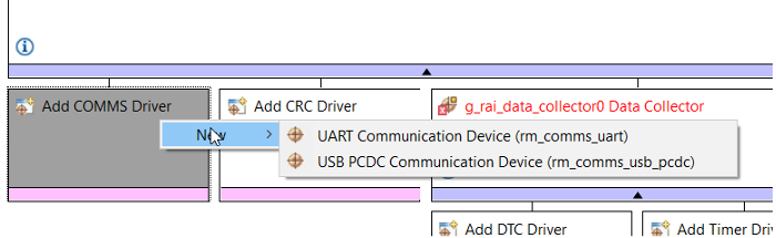
Step 2.12: Add USB PCDC Communication Device
- Under the Data Shipper module:
- Click Add COMMS Driver > New > UUSBSB PCDC Communication Device (rm_comms_usb_pcdc).
-
On the Properties tab, configure the following for
g_timer0 Timer, General PWM (r_gpt):- General > Period:
500 - General > Period Unit:
Microseconds - Interrupts > Overflow/Crest Interrupt Priority:
Priority 12
- General > Period:
-
In
r_usb_basic, on the Properties tab, set the following:- Module > USBFS Interrupt Priority:
Priority 10 - Module >USBFS Resume Priority:
Priority 10 - Module >USBFS D0FIFO Interrupt Priority:
Priority 10 - Module > USBFS D1FIFO Interrupt Priority:
Priority 10
- Module > USBFS Interrupt Priority:
Step 2.13: Add Timeout Timer (r_gpt)
- Navigate to New Stack > Timers > Timer, General PWM (r_gpt).
- On the Properties tab, configure the following:
- General > Name:
g_timeout_timer2 - General > Channel:
2 - General > Mode:
One-Shot - General > Period:
250 - General > Period Unit:
Milliseconds - Interrupts > Callback:
gpt_timeout_callback - Interrupts > Overflow/Crest Interrupt Priority:
Priority 13
- General > Name:
Step 2.14: Add LED Timer (r_gpt)
- On the Properties tab, configure the following:
- General > Name:
g_led_timer1 - General > Channel:
1 - General > Mode:
Periodic - General > Period:
250 - General > Period Unit:
Milliseconds - Interrupts > Callback:
rai_led_timer_callback - Interrupts > Overflow/Crest Interrupt Priority:
Priority 15
- General > Name:
Step 2.15: Generate Project Content
- Click Generate Project Content (top-right).
- When prompted, check Always save and generate without asking and click Proceed.
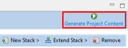
- The FSP Configurator will extract all the necessary drivers and generate the code based on the configuration provided in the Properties tab.
Step 2.16: Copy Source Files
-
In Project Explorer, expand the
srcfolder and copy in the following files:hal_entry.c(overwrite existing file)hal_entry.hr_usb_pcdc_descriptor.crai_led.c
-
Folders:
realityai\\rm_icm42670\\SEGGER_RTT\\
-
Outside the
srcfolder, copy theOutputfolder (contains recorded data for model creation).
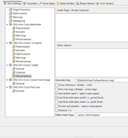
Step 2.17: Enable Float and Nano Printf Support
- Right-click the project folder > Properties > C/C++ Build > Settings.
- Navigate to Tool Settings > GNU Arm Cross C Linker > Miscellaneous:
- Enable:
Use float with nano printf (-u_printf_float)Use Newlib-nano (--specs=nano.specs)
- Enable:
- Click Apply.
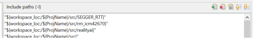
Step 2.18: Add Include Paths
- Go to C/C++ Build > Settings > GNU Arm Cross C Compiler > Includes tab.
- Add the following paths:
${workspace_loc:/${ProjName}/src/SEGGER_RTT}${workspace_loc:/${ProjName}/src/rm_icm42670}${workspace_loc:/${ProjName}/src/realityai}
- Click Apply.
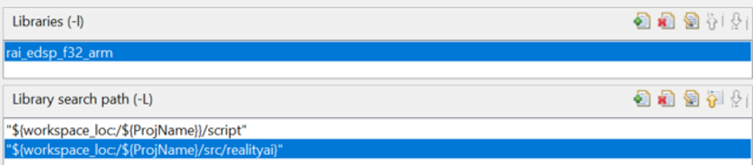
Step 2.19: Link the Reality AI Library
- Go to C/C++ Build > Settings > GNU Arm Cross C Linker > Libraries:
- Add the realityai folder to the library search path:
${workspace_loc:/${ProjName}/src/realityai}
- Add the Reality AI library to the Libraries list:
rai_edsp_f32_arm
- Add the realityai folder to the library search path:
- Click Apply.
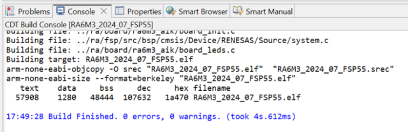
Step 2.20: Build the Project
- Click the Build icon (hammer).
Step 2.21: Verify Build Output
- Ensure the Console pane in the lower-right corner of e² Studio shows zero errors and warnings.
Step 2.22: Program the AIK Board
The application is now ready to be programmed and run on the AIK kit.
- Verify the accelerometer is connected to PMOD 1.
- Click the Debug icon (bug) or right-click the launch file and start debugging.
Step 2.23: Start and Stop Application Execution
- Click Resume or press F8 to start the application.
- To stop execution, click Terminate or press Ctrl + F2.
Step 3: Data Collection
This section explains how to collect data using the Reality AI Eclipse plugin with e² studio.
Ensure that the previous setup steps are completed before proceeding.
Step 3.1: Connect the AIK-RA6M3 device
Connect the USB Type-C COM port (J11) of the AIK-RA6M3 device to your computer.
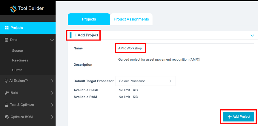
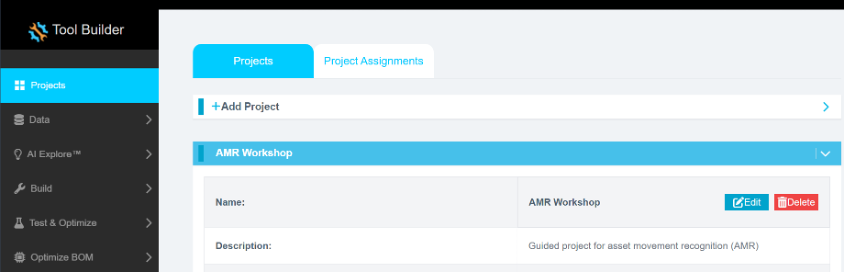
Step 3.2: Create a new project in Reality AI Tools
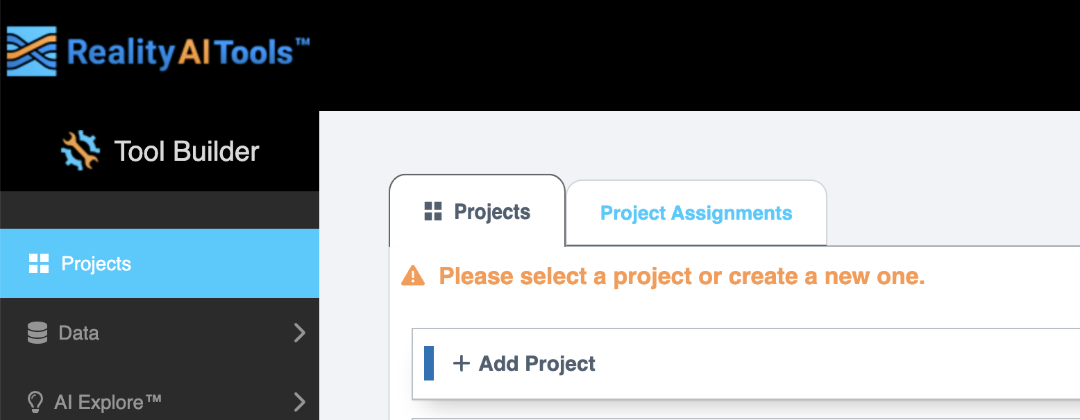
- Open the Reality AI Tools platform.
- Click + Add Project to expand the project creation panel.
- Enter a Name for the new project and an optional Description.
- Click the + Add Project button at the bottom right to create the project.
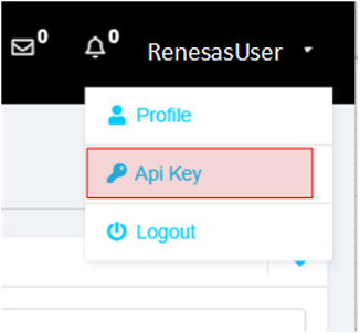
Step 3.3: Retrieve your API key
- Navigate to your username at the top-right corner of the screen.
- Select API Key Option from the dropdown menu.
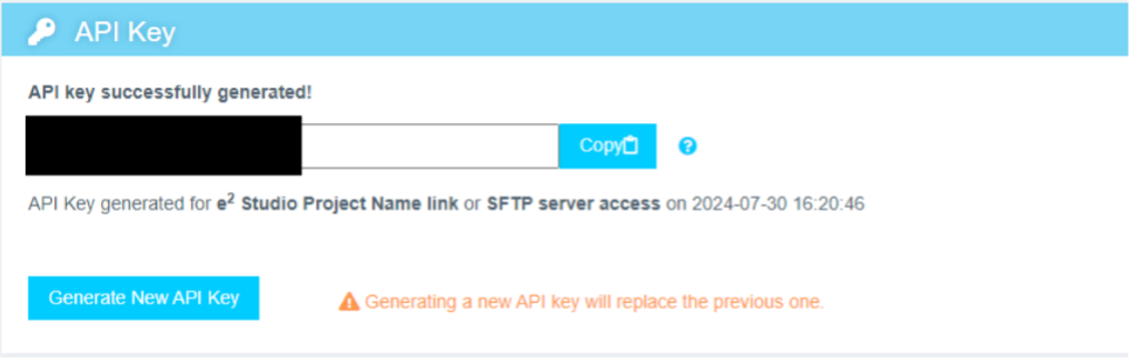
Step 3.4: Copy the API key
Copy the API key to your clipboard. This key is required to link e² studio IDE with Reality AI Tools.
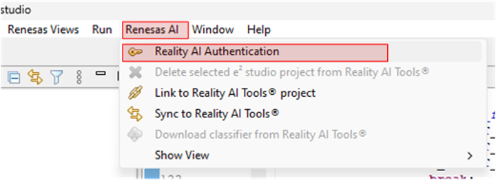
Step 3.5: Authenticate Reality AI Tools in e² Studio
- In
e² studio, go to Renesas AI > Reality AI Authentication.
Note: If the “Renesas AI” menu does not appear, refer to the Appendix for troubleshooting steps.
- Enter your Username and API key.
- Click
Apply and Close.
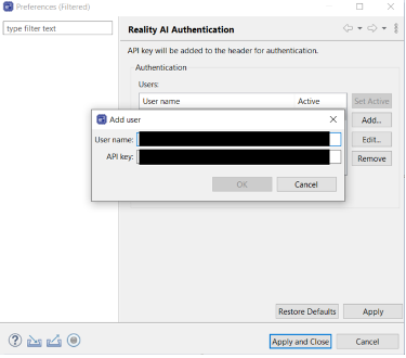
The IDE is now connected to the Reality AI platform.
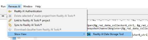
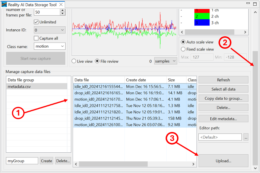
Step 3.6: Open the Reality AI Data Storage Tool
- From the main menu, select Renesas AI > Show View > Reality AI Data Storage Tool.
- A new window appears in the bottom pane.
- Drag this view to the main area by clicking its tab and moving it to the central tab group.
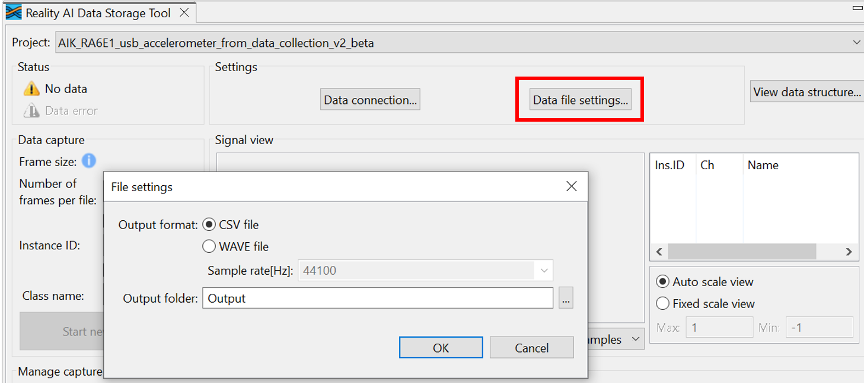
Step 3.7: Configure data file settings
- Click Data file settings in the tool.
- Verify the CSV file format and the Output folder location (relative to the project).
- Click OK to close the dialog box.
- Select the correct
e² studioproject from the dropdown menu. - Click Data Connection.
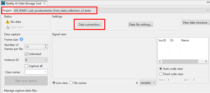
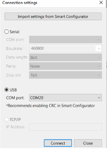
Step 3.8: Connect the USB COM port
In the Connection Settings dialog box:
- Select USB as the connection type.
- Choose the appropriate COM port.
- Click Connect, then Close.
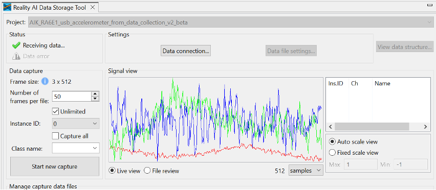
Step 3.9: Verify signal data
In the Reality AI Data Storage Tool, verify the presence of a waveform in the Signal View pane.
If no waveform is visible:
- Click File Review, then Live View.
If the issue persists, review all prerequisite steps to confirm hardware and software connections.
You should see:
- A green checkmark
- A "Receiving data..." indicator
- A waveform in the Signal View window
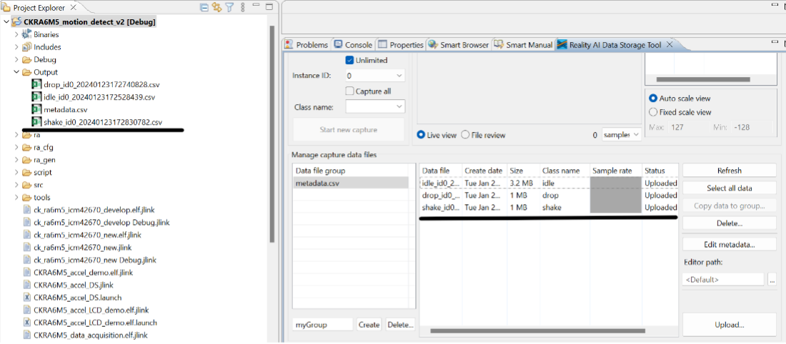
Step 3.10: Understand how data is stored
The tool saves files in the project’s Output folder.
- This folder may already include previously collected lab data.
- Files include date and time metadata.
- You will collect additional data in the upcoming steps.
Two collection modes:
- Unlimited: Captures data until manually stopped
- Number of frames per file: Stops automatically at a preset frame count
For this project, 200 frames ≈ 52 seconds of data.
The following steps use Unlimited mode.
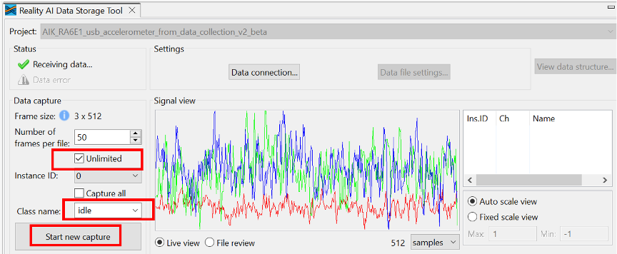
Step 3.11: Collect "idle" class data
To collect accelerometer data for the idle class:
- In the tool, select the Unlimited checkbox.
- Set Class Name to
idle. - Click Start New Capture.
- Keep the board stationary for 60 seconds.
- Click Stop Capture.
You should see a new data file labeled idle in the Manage capture data tab.
Step 3.12: Collect "drop" class data
- Set Class Name to
drop. - Click Start New Capture.
- Drop the board from ~7 cm repeatedly for 1–2 minutes.
⚠️ Avoid letting the PMOD connector hit the surface.
Use a mouse pad or soft material as padding.
- Click Stop Capture.
- Confirm that a new file is labeled
drop.
Additional files from sample data may appear.

Step 3.13: Collect "motion" class data
- Set Class Name to
motion. - Click Start New Capture.
- Move the board by:
- Sliding it across a table
- Lifting, rotating, or shaking it
- Capture for approximately 60 seconds.
- Click Stop Capture.
A new file labeled motion should now appear.
Step 3.14: Confirm data availability
You should now have data files for:
idledropmotion
If you previously copied the Output folder (see Step 2.16), additional pre-collected data is included.
If not:
- Manually merge your
metadata.csvwith the supplemental one from the copied data.
To upload:
- Use
Ctrl + Clickto select data files (include supplemental if applicable). - Scroll down in the Data Storage Tool.
- Click the Upload button at the bottom right.
Step 3.15: Upload to Reality AI Tools
- A dialog will list available projects.
- Select your project in the Destination Reality AI Tools project field.
- Set Sampling rate[Hz] to
1600 Hz. - Click OK.
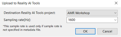
The data and metadata will upload. A confirmation dialog appears upon successful upload.
Step 4: Creating Models
- Version 5.6.6
- Version 6.0
This section explains how to create AI models using the dataset collected in earlier steps. A Reality AI Tools account is required.
Step 4.1: Log In to Reality AI Tools
If not already logged in, visit https://portal.reality.ai/login and enter the provided password.
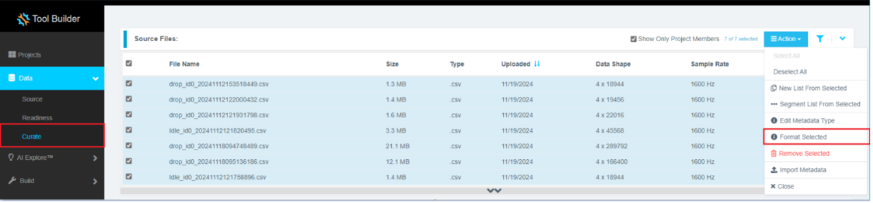
Step 4.2: Format the Data
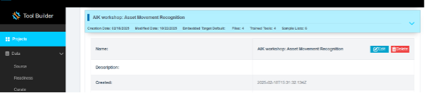
- In Reality AI Tools, click your current asset movement project to set it as active.
- The Project indicator on the top ribbon will update to reflect the selected project.
- Click the Data tab on the left pane.
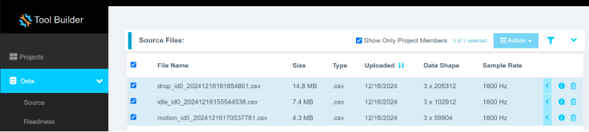
- Expand the Curate tab.
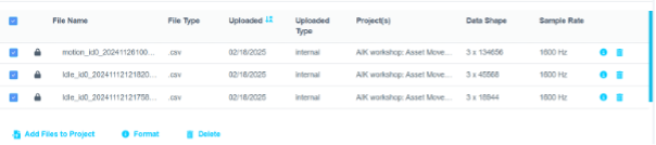
- Expand Source Files.
- Select the checkbox next to File Name to select all files.
- Click Action, then select Format Selected.
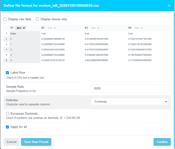
Formatting steps:
- Click the drop-down on the first column (default shows
Data). - Scroll down using the scroll bar or mouse wheel.
- Select
Ignoreto exclude the index column. - Click Confirm to complete file formatting.
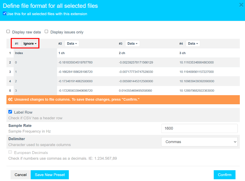
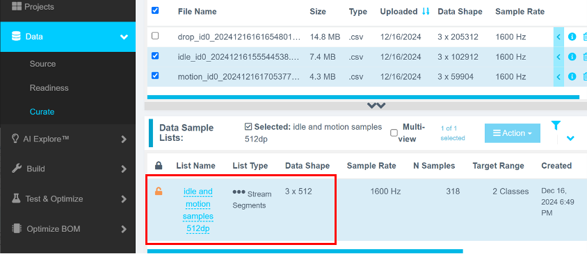
Step 4.3: Verify Data Shape and Sample Rate
Ensure that:
- The data shape is
3 × {number of samples} - The sample rate is
1600 Hz
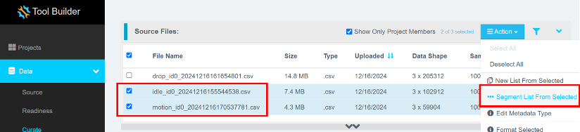
Step 4.4: Segment the Data
Segmenting Idle and Motion Data
- Select all
idleandmotionfiles (excludedropfiles). - Click Action > Segment List From Selected.
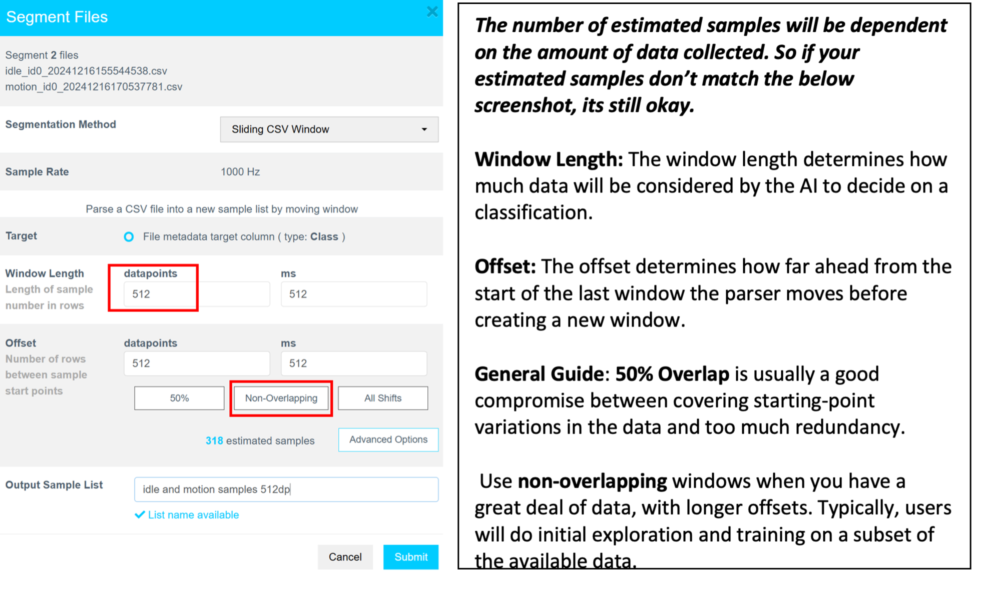
Why Segmentation?
Segmentation is required to create models that run efficiently on Renesas MCUs. These models analyze short data windows (e.g., 1 s or 500 ms) to provide rapid predictions, reducing memory and CPU requirements.
The AI Explore engine uses segmented sample buffers to extract features and train models.
Segmentation steps:
- Set Window Length to
512datapoints. - Click Non-Overlapping to auto-fill the Offset field.
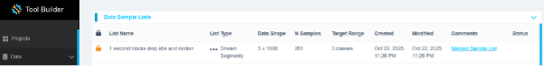
- Enter a meaningful name for the sample list in the Output Sample List field.
- Click Submit.
After submission, the new sample list appears under Data Sample Lists. If not, refresh the page.
Segmenting Drop Data Using Energy Triggering
- In Data > Curate, select the
dropfile(s). - Click Action > Segment List From Selected.
- In Segmentation Method, select Energy Triggered.
- Set Trigger Channel to
Magnitude. - Click Show Preview.
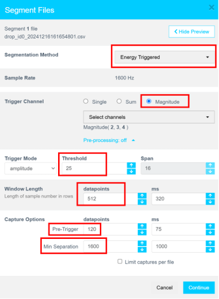
Set the following parameters:
- Trigger Mode: Amplitude
- Threshold: 25
- Window Length: 512
- Pre-Trigger: 120
- Min Separation: 1600
- Click Refresh Preview.
Confirm:
- Trigger spikes are visible.
- Drop events are highlighted in blue.
- Zoom in to review data (e.g., only show first 32,000 datapoints).
- Adjust Threshold and Min Separation if necessary.
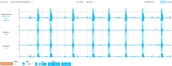
- Once satisfied, click Continue.
- Name the output sample list and click Submit.
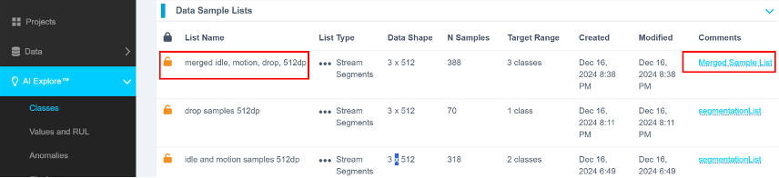
Step 4.5: Merge Sample Lists
- In Data > Curate > Data Sample Lists, use
Ctrl + Clickor enable Multi-view to select both theidle/motionanddropsample lists. - Click Action > Merge Selected to New.
- Provide a descriptive name and click Create.
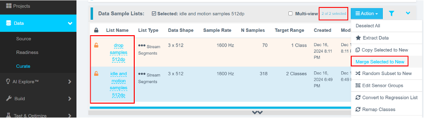
You should now see three sample lists:
- The original
idle/motionsample list - The energy-triggered
droplist - The merged list containing both
Model Types in Reality AI Tools
Reality AI Tools support three types of models:
- Classes: Supervised classification of labeled data (used in this tutorial)
- Values: Regression models to compute continuous values (e.g., temperature)
- Anomalies: Semi-supervised models requiring only normal data to detect anomalies
Step 4.6: Run AI Explore
- Navigate to AI Explore > Classes.
- Select the merged data sample list.
- Click Start Exploring.
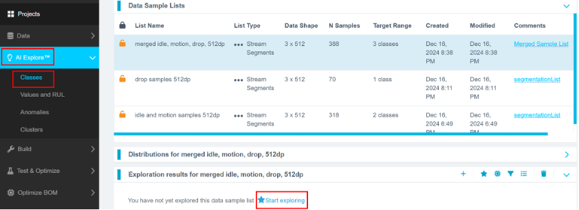
An In Progress status will appear. The process may take 5–20 minutes.
What Happens in the Background
- A balanced subset is created from your data sample list.
- Multiple feature sets and ML models are evaluated.
- Top-performing candidates undergo 10-fold cross-validation.
K-Fold Validation:
The dataset is split into 10 parts. In each round, 9 parts train the model and 1 part is used for testing. This repeats until all 10 parts have been used for testing. Accuracy is averaged across these 10 iterations.
You can later retrain using the full, imbalanced dataset under Build > Train.
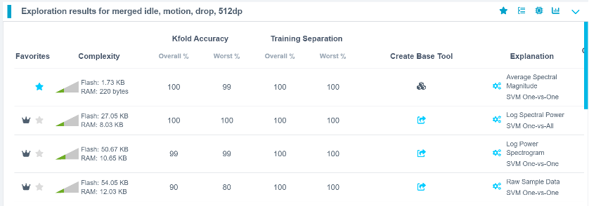
Step 4.7: Review Candidate Models
Once exploration completes:
- Several candidate models are shown.
- Best options may not always be at the top (e.g., 4th and 6th models may have high accuracy and lower resource usage).
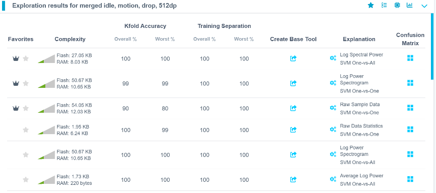
- Select your preferred model.
- Provide a name or accept the suggested one.
- Click Add to create a Base Tool.
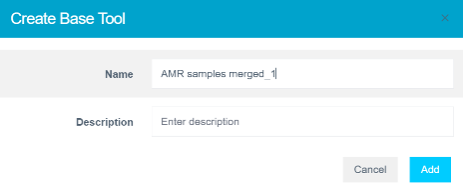
The model icon will update to indicate a successful creation.
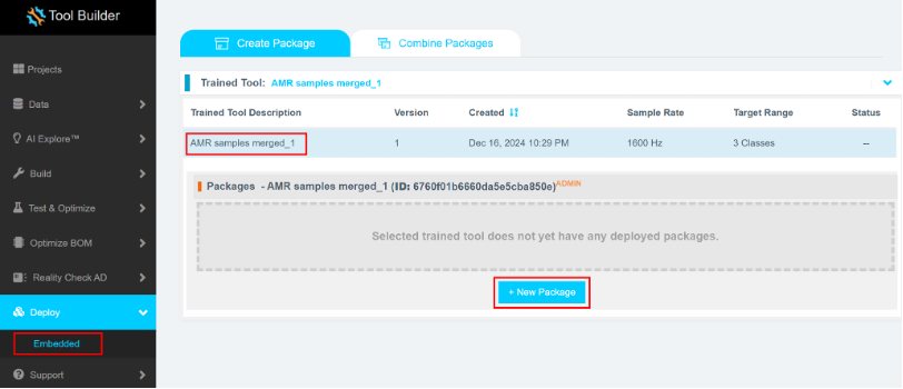
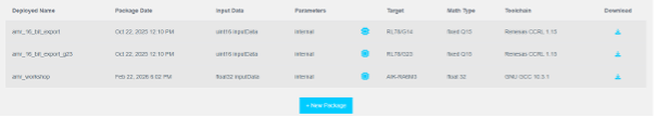
Step 4.8: Deploy the Model
- Click Deploy > Embedded.
- Open Trained Tool Description.
- Click + New Package.
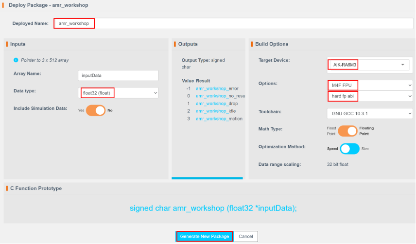
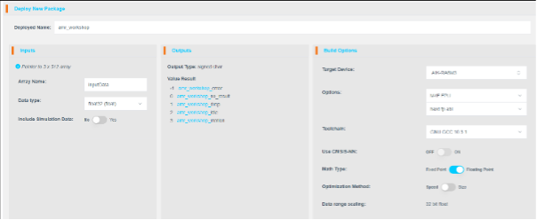
Deployment settings:
- Set Deploy Name to
amr_workshop(to match the code in Section 2). - Click Generate New Package.
Package generation takes 5–15 minutes.
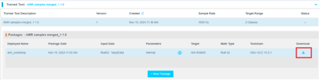
Step 4.9: Download and Integrate the Model
- Once the package is ready, click the download icon.
- Refresh the page if needed.
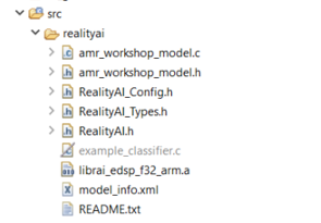
The .zip archive will contain 7 files.
Copy all files except:
example_classifier.creadme.txt
to the following directory: src\realityai\ in the e² studio project workspace. Overwrite the existing files.
Alternative Method
- In Project Explorer, select your project.
- Navigate to Renesas AI > Download inference module from Reality AI Tools.
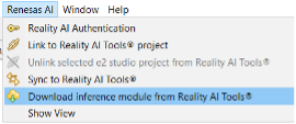
- Select the recently deployed model.
- Click Download.
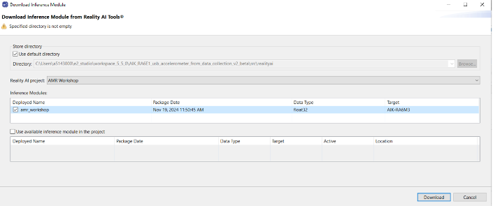
Note: File names may vary depending on the project name.
Model function calls are specified in amr_workshop_model.h.
This section explains how to create AI models using the dataset collected in earlier steps. A Reality AI Tools account is required.
Step 4.1: Log In to Reality AI Tools
If not already logged in, visit https://portal.reality.ai/login and enter the provided password.
Step 4.2: Format the Data
-
In Reality AI Tools, click your current asset movement project to set it as active.
-
The Project indicator on the top ribbon will update to reflect the selected project.
-
Click the Data tab on the left panel.
-
Expand Source Files.
-
Select the checkbox next to File Name to select all files. Ensure that:
- The data shape is 3 × number of samples
- The sample rate is 1600 Hz
- Select Format.
Formatting steps:
- Click the drop-down on the first column (default shows
Data). - Scroll down using the scroll bar or mouse wheel.
- Select
Ignoreto exclude the index column. - Click Confirm to complete file formatting.
Step 4.3: Data sample lists
- Click Deploy > Embedded.
- Open Trained Tool Description.
- Click + New Package.
Why Segmentation?
Segmentation is required to create models that run efficiently on Renesas MCUs. These models analyze short data windows (e.g., 1 s or 500 ms) to provide rapid predictions, reducing memory and CPU requirements.
The AI Explore engine uses segmented sample buffers to extract features and train models.
Step 4.4: Deploy the Model
Deployment settings:
- Set Deploy Name to
amr_workshop(to match the code in Section 2). - Click Generate New Package.
Package generation takes 5–15 minutes.
Step 4.9: Download and Integrate the Model
- Once the package is ready, click the download icon.
- Refresh the page if needed.
![]()
Step 5: Deploying the Model
This section explains how to deploy the trained model to the AIK-RA6M3 hardware and verify its performance. It includes steps to integrate the model with the existing project, build the application, and test real-time predictions using onboard LEDs.
Step 5.1: Continue from the Previous Steps
Ensure that the model has been successfully downloaded from the Reality AI Tools portal and that the project files are in place.
Step 5.2: Generate Project Content
- In e² Studio, open the
configuration.xmlfile located in the project root. - Click Generate Project Content to update the project with the current configuration settings.
Step 5.3: Update hal_entry.h with Model Header
-
Open the
hal_entry.hfile. -
Import the model header file using
#include.If your deployed model is named
amr_workshop_model.h, no changes are required (except commenting out any references to unused classes likecircleorwave).If your model has a different name, update the file name in the
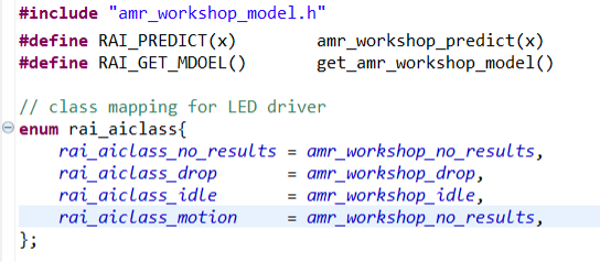
#includedirective and revise the macros accordingly:#include "amr_workshop_model.h"
#define RAI_PREDICT(x) amr_workshop_predict(x)
#define RAI_GET_MODEL() get_amr_workshop_model()
enum rai_aiclass {
rai_aiclass_no_results = amr_workshop_no_results,
rai_aiclass_drop = amr_workshop_drop,
rai_aiclass_idle = amr_workshop_idle,
rai_aiclass_motion = amr_workshop_motion
};
This ensures the model functions and class enumerations are correctly mapped for inference.
Step 5.4: Clean Up Unused Classes in rai_led.c
- Open the
rai_led.cfile. - Remove any references to unused AI classes (e.g.,
circle,wave) from therai_led_set_state()function. - Ensure only valid predictions (
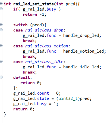
drop,motion,idle) are handled:
int rai_led_set_state(int pred) {
    if (g_rai_led.busy)
        return -1;

    switch (pred) {
        case rai_aiclass_drop:
            g_rai_led.func = handle_drop_led;
            break;
        case rai_aiclass_motion:
            g_rai_led.func = handle_motion_led;
            break;
        case rai_aiclass_idle:
            g_rai_led.func = handle_idle_led;
            break;
        default:
            return 0;
    }

    g_rai_led.count = 0;
    g_rai_led.state = (uint32_t)pred;
    g_rai_led.busy = 1;
    return 0;
}
Step 5.5: Troubleshooting – Poor Model Performance
If the model does not perform well:
- Collect additional data for all classes and retrain the model. This often improves performance across varied conditions.
- Verify consistency between your training data collection and real-time testing methods.
- Ensure balanced class coverage by capturing more representative samples.
Step 5.6: Build the Project
- Click the Build icon (hammer) in the toolbar to compile the project.
- Ensure the build completes without errors.
Step 5.7: Start Debug Session
- Click the Debug icon (bug) to flash the compiled binary to the AIK kit.
- Alternatively, right-click the
.launchfile and choose
Debug As > Renesas GDB Hardware Debugging.
Step 5.8: Run the Application
- Click Resume or press F8 to begin application execution.
Step 5.9: Observe Inference via LED Indicators
Move the AIK-RA6M3 board and observe the LED behavior as shown below:
| No. | Movement | LED Indicator |
|---|---|---|
| 1 | Drop | Red LED blinks |
| 2 | Idle | Green LED on |
| 3 | Motion | Light Blue LED on |
These LEDs reflect the real-time predictions of your deployed model.
Appendix
This section provides troubleshooting guidance if Reality AI menu items are not visible in the e² Studio title bar. It also explains how to use the Reality AI Monitor to view real-time inference outputs from the deployed model.
Step A: Install Reality AI Features
If Reality AI items are not available in e² Studio, follow these steps:
-
From the main menu, go to
Help > Install Renesas IDE Features... -
In the dialog that appears, select Reality AI features from the available list.
-
Click Finish to begin the installation process.
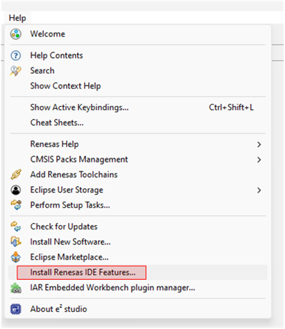
- Restart e² Studio when prompted to apply the changes.
Step B: Configure Reality AI Monitor
Once the Reality AI features are installed and e² studio has restarted, complete the following steps to view inference outputs in real time:
- Launch the Reality AI Monitor window from the Renesas AI menu.
- In the Settings tab:
- Select the e² Studio project that was created in the previous section.
- In the Inference Module dropdown, select the deployed model that was created using Reality AI Tools.
- Navigate to the Data Connection tab and connect to the board using the appropriate COM port.
Output
Once connected, the Reality AI Monitor will begin displaying real-time inference results from the AIK-RA6M3 board. This allows you to visually validate and monitor the model’s predictions while performing different movement-based actions.