Finger friction demo
- Renesas RA6T2
- Renesas RA8T1
Introduction - RA6T2
This tutorial covers the development and testing of the Finger Friction Demo, an AI model that can detect when friction is applied to a motor shaft using only vibration data, using the Renesas RA6T2 Flexible Motor Control Kit and the Reality AI Tools portal. The Reality AI Tools portal enables the generation of AI models for non-visual sensing applications.
Objectives
This tutorial aims to provide hands-on experience in developing a simple AI demo using the Renesas RA6T2 motor kit and Reality AI Tools.
Section 1: Prerequisites
This section outlines the hardware and software prerequisites for running the Finger Friction demo.
Hardware and Software Requirements
This tutorial requires the RA6T2 Flexible Motor Control Kit (MCK-RA6T2).
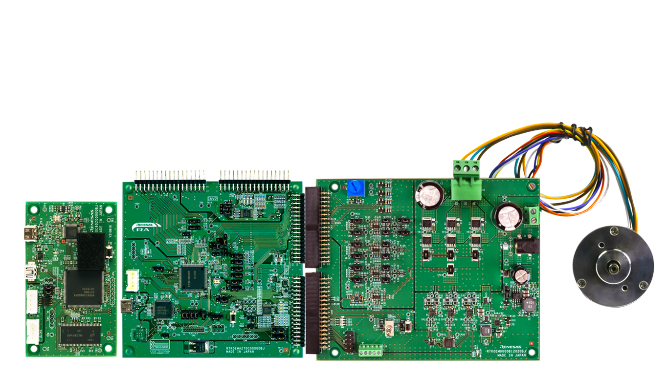
The MCK-RA6T2 is a development kit that enables easy evaluation of motor control using permanent magnet synchronous motors (brushless DC motors). With this product and the sample code and QE for Motor that can be downloaded from the website, you can start evaluating motor control using the RA6T2 right away.
The MCK-RA6T2 kit includes:
- RA6T2 board
- DC brushless motor (Moon's Industries)
- Communications board (not used in this demo)
- Necessary USB cables
Additional components:
- 36 V power supply (recommended but not required. Click to access similar product link)
- USB to UART cable (required. Click to access similar product link)
Software Required:
- PC with Windows® 10 or 11
- Project files provided by Renesas - Reality AI team. You can download the project here.
- Renesas e² Studio IDE 2023-10 or newer with FSP 5.6
- Reality AI Tools account
- Sample dataset
Kit Assembly
Follow these steps to assemble the kit:
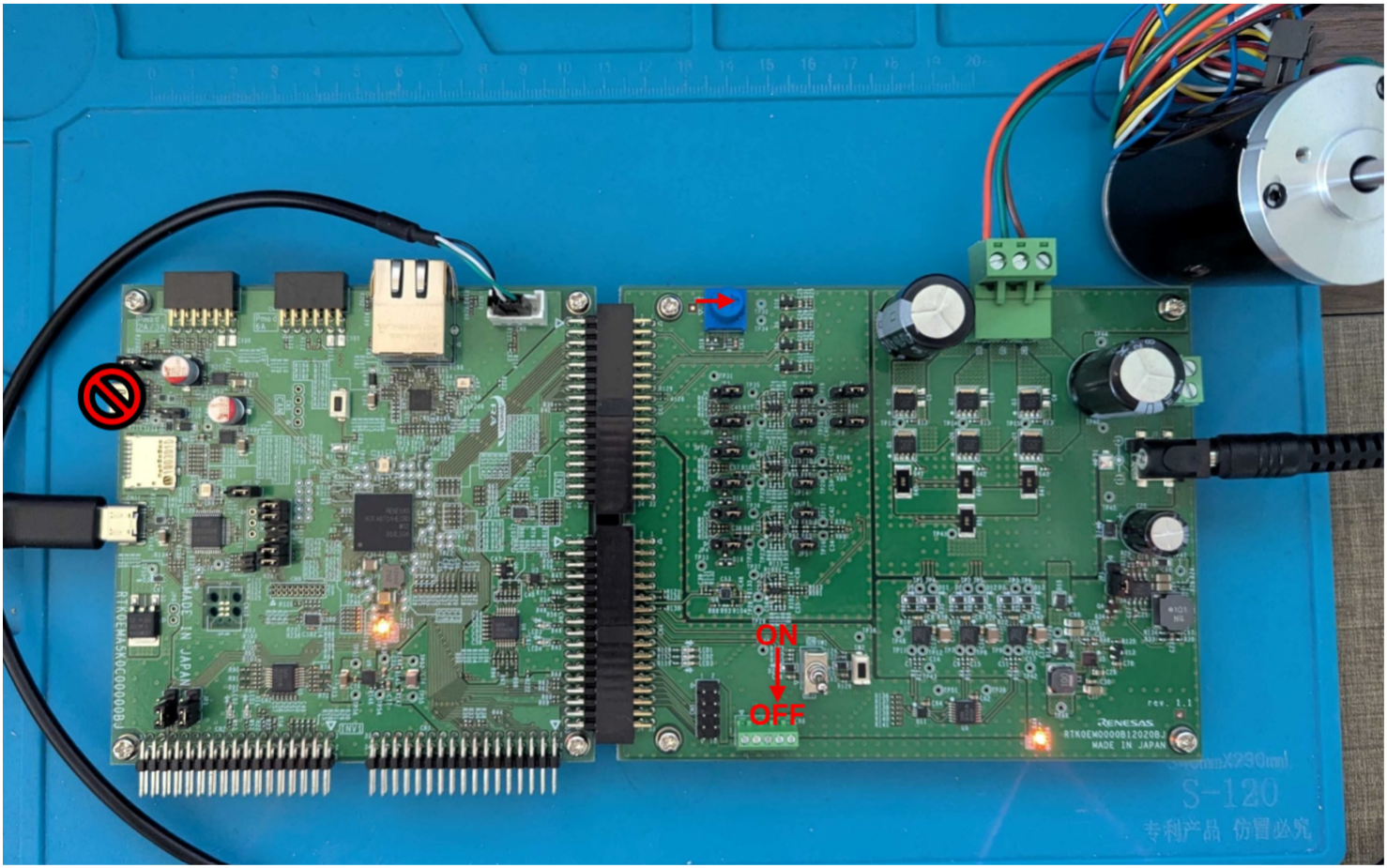
- Ensure the toggle switch is in the OFF position, and all jumpers are in their default settings.
See the documentation that came with the kit if there is concern that the board may not be in the default configuration.
- Connect the PC to USB-C on the board
- Connect the external power supply (optional).
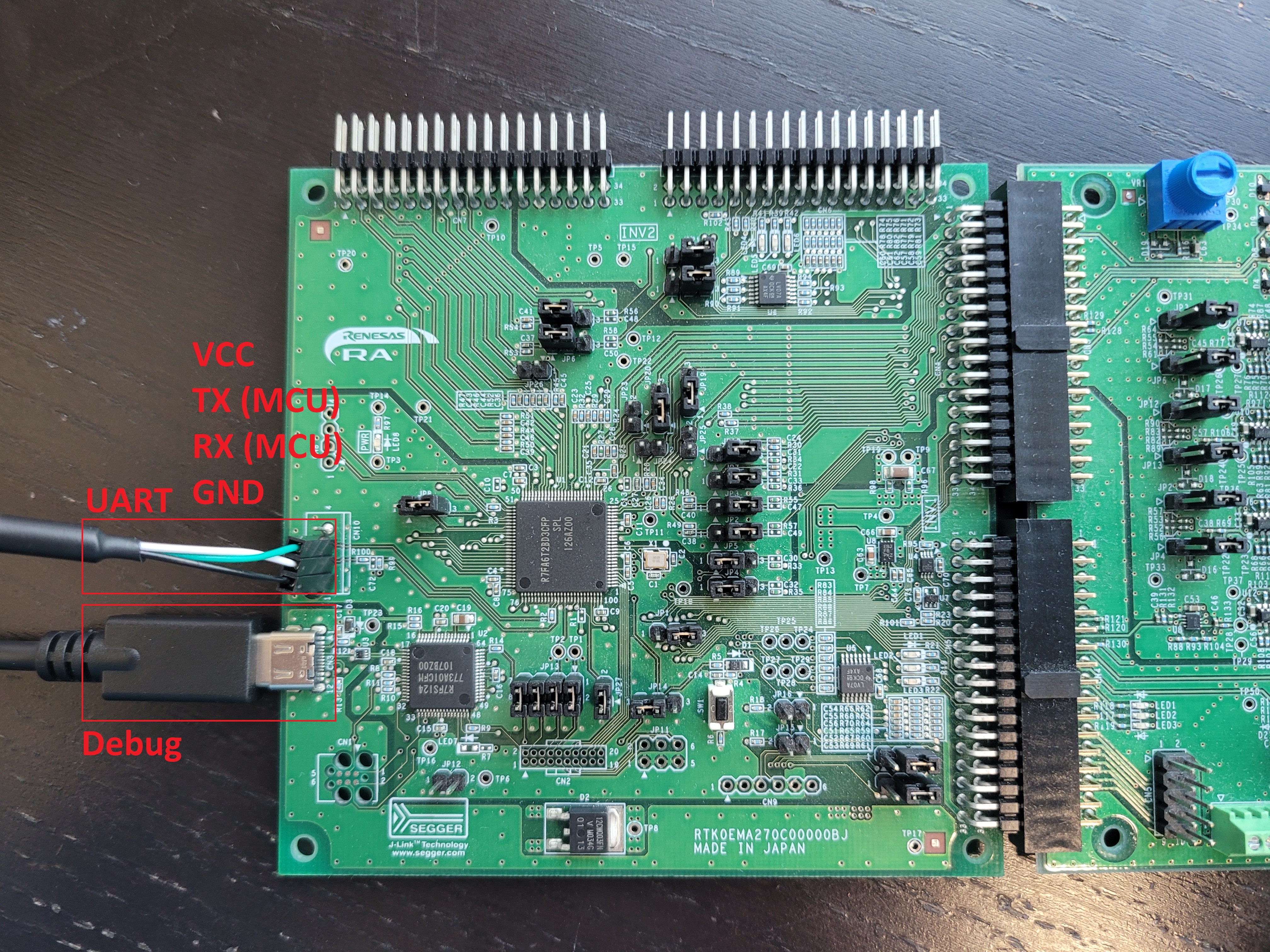
- Connect USB to UART via CN10. Refer to the following table for pin connections:
| Pin Reference | Connection |
|---|---|
| Pin 4 | VCC (No connection) |
| Pin 3 | TX to RX (Green wire) |
| Pin 2 | RX to TX (White wire) |
| Pin 1 | GND to GND (Black wire) |
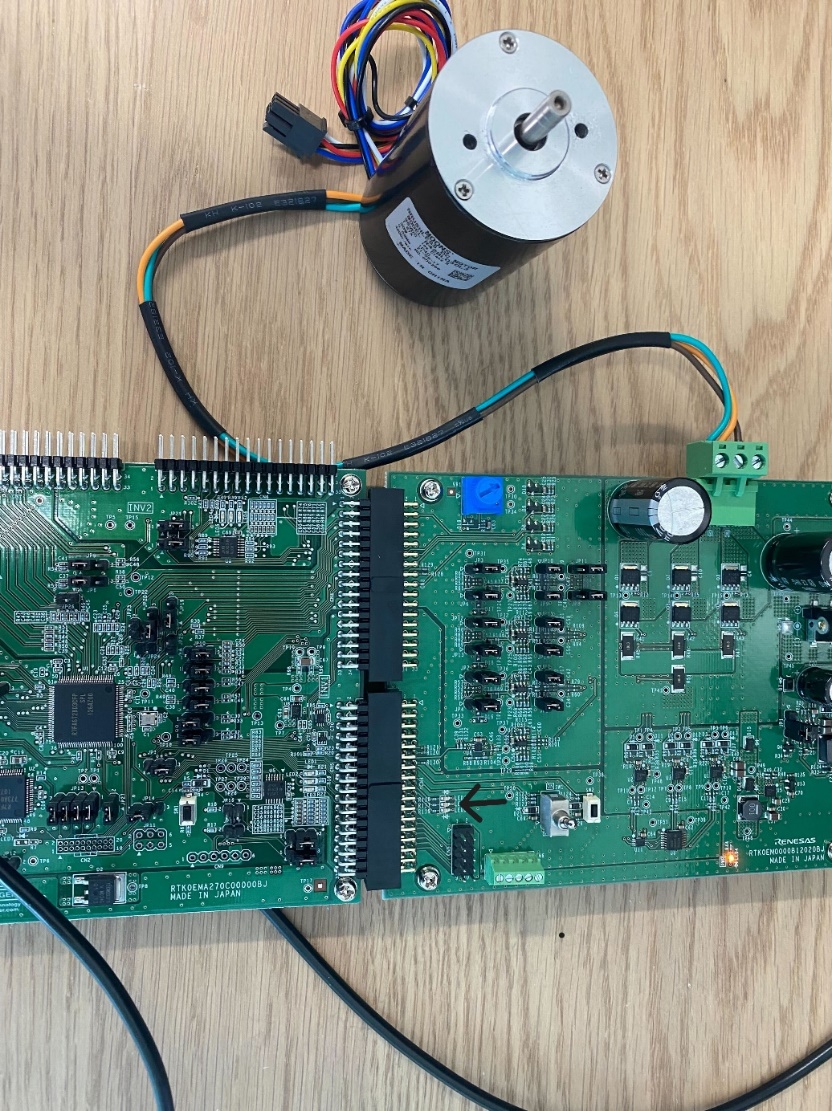
- Connect the motor to CN2.
| Pin | Name | Colour | Description |
|---|---|---|---|
| 1 | GND | Black | Device ground supply |
| 2 | TXD | White | Transmit Asynchronous Data |
| 3 | RXD | Green | Receive Asynchronous Data |
- Install Renesas e² Studio IDE 2024-10 or newer. Take note of where e² Studio is installed.
- Create a Reality AI Tools account.
- Login to Reality AI Tools using the username and password provided.
Contact Renesas for account credentials and access documentation, if needed.
 9. Leave the Reality AI Tools browser window open in the background.
Section 2: Data Collection
This section describes how to collect data using the Reality AI Eclipse plugin in e² Studio.
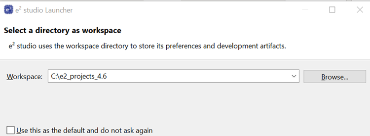
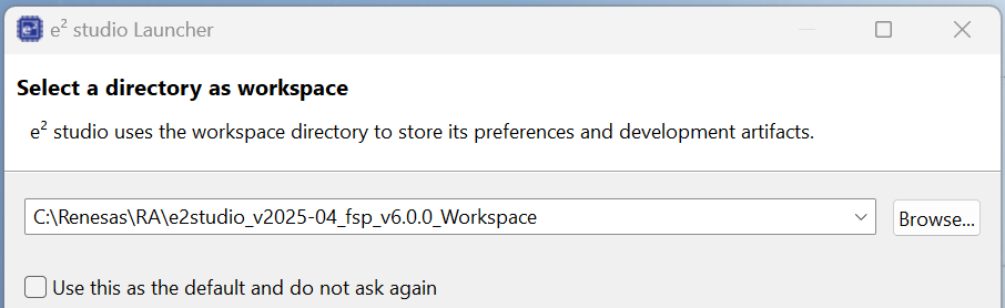
- Open e² Studio IDE and select a workspace (e.g.,
C:\e2_projects_4.6).
This tutorial assumes the above workspace path, but any location is acceptable.
-
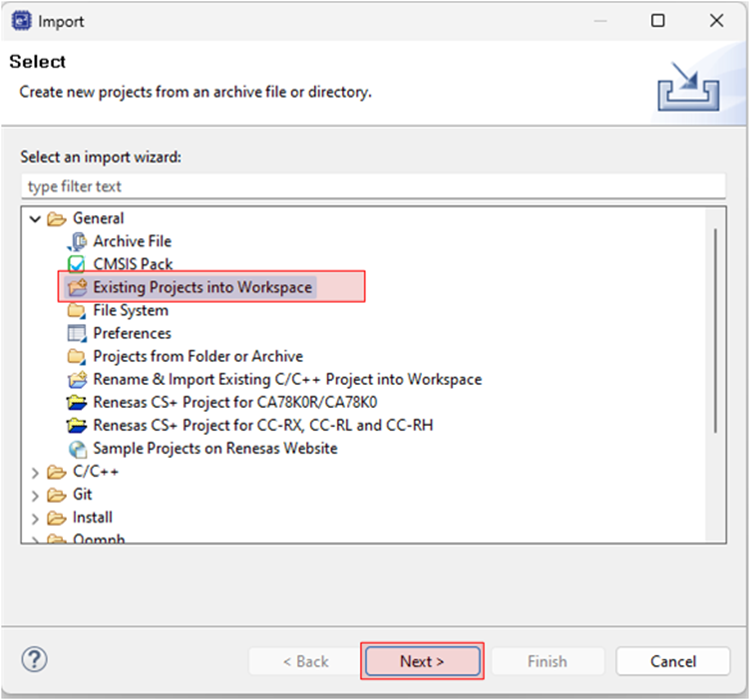
Navigate to File > Import.
-
Select General > Existing Projects into Workspace.
-
Click Next to continue.
-
Select the Select archive file radio button and navigate to the zip file for this tutorial. Ensure the project is selected and click Finish.
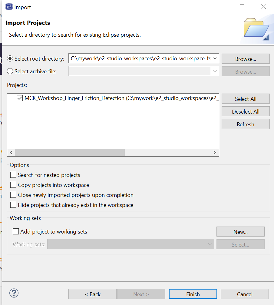
The demo project is imported into the workspace.
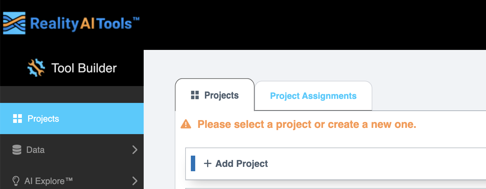
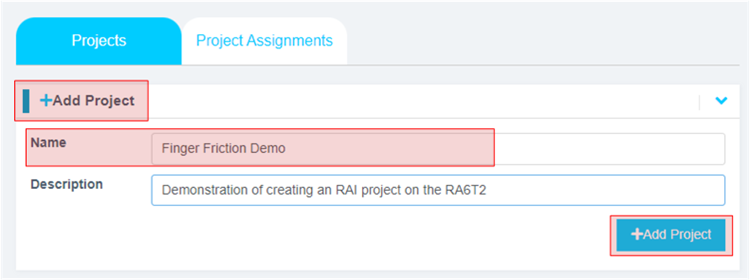
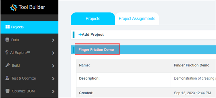
6. In the Reality AI Tools portal:
i. Click +Add Project.
ii. Enter a name and optional description.
iii. Click the +Add Project button in the lower right corner.
If you have explorer subscription, use the existing MCK workshop: Finger Friction Detection project available in your account to upload and analyze the data.
-
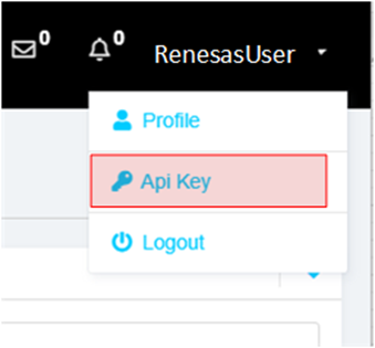
To retrieve the API key, click your username on the top-right of the screen and select API Key option.
-
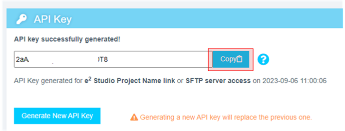
Copy this API key to the clipboard. This key will be used to connect e² Studio IDE and Reality AI Tools.
-
In e² Studio and navigate to Renesas AI > Reality AI Authentication.
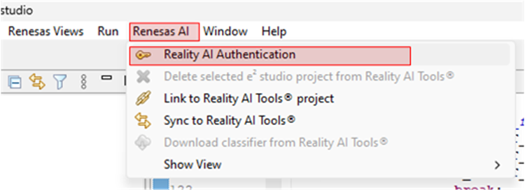
If Renesas AI does not appear in the menu, consult the appendix section.
-
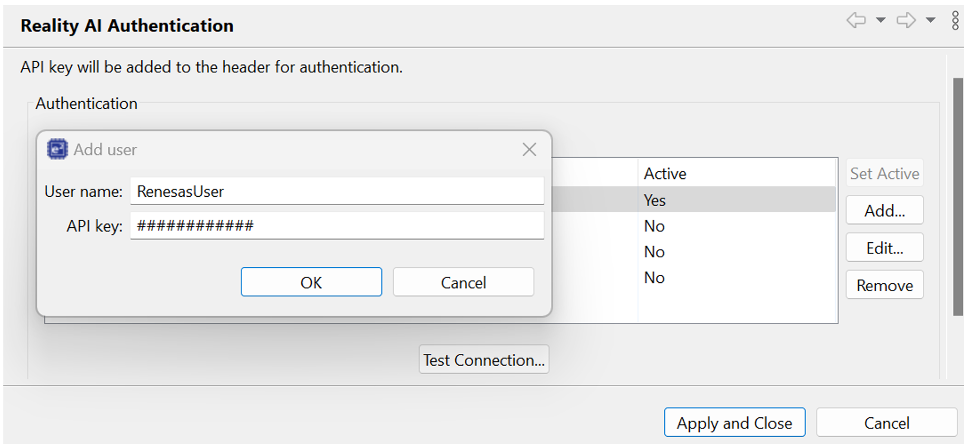
Paste the API key and click OK. To verify this, click Test Connection. Once confirmed, click Apply and Close. The IDE can now connect to the Reality AI site.
-
Navigate to Renesas AI > Reality AI > Reality AI Utilities > Data Storage Tool. A new window will open in the bottom pane. Drag the new view to the main area for better visibility.
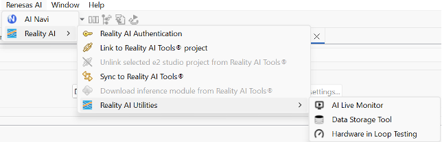
-
A new view opens in the bottom pane. Drag this view to the main editor area by clicking its tab and dropping it into the main view. In the view, select your project from the dropdown and choose Data File Settings…. Set Output folder to Output. This creates the default Output folder at the project root.

-
Select the project from the drop-down list and then click the Data Connection button.
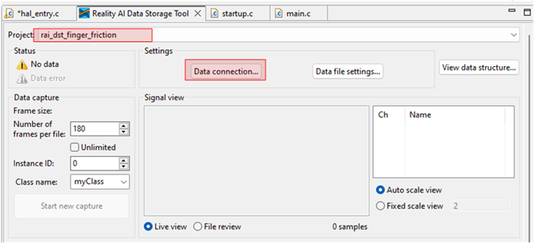
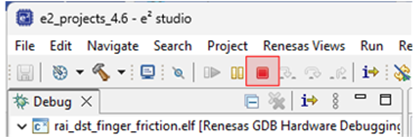
The name of the e²-studio project is MCK_Workshop_Finger_Friction_Detection. However, older version of the workshop had the project named rai_dst_finger_friction. Both projects implement the same functionality with minor changes.
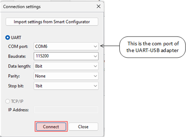
- In the Connection settings dialog:
- Select the COM port,
- Set the Baud rate to
115200 - Use the communication protocol parameters
8bit-None-1bit. - Click Connect and then Close.
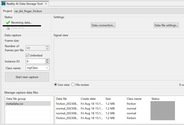
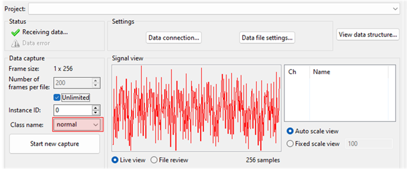
- Once connected, the status (top left) should show "Receiving data..." with a check mark.
A green check mark at the top-left indicates a successful connection—not necessarily that data is being received.
- If using project:
rai_dst_finger_friction, expand the project in the Project Explorer view and openhal_entry.c. EnsureUSE_SHIPPERis defined as1. This will build the project in the data collection mode.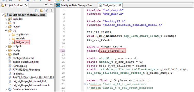 If using project:
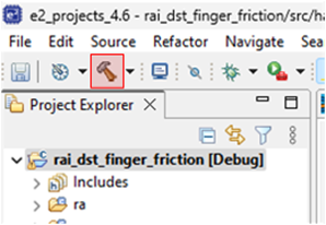
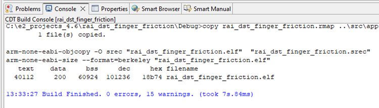
 MCK_Workshop_Finger_Friction_Detection, navigate tosrc>dcds.hand ensureDCDS_ENABLE_SHIPPERis defined as1. - Save the file and build the project by clicking the hammer icon. The project should build without error. Warnings may appear; they are expected.
-
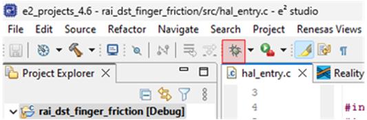
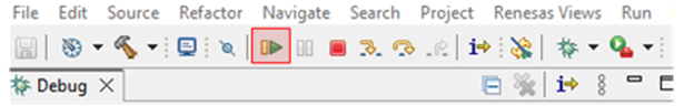
Ensure the toggle switch is OFF. Start a debug session by clicking the Debug icon in the toolbar.
-
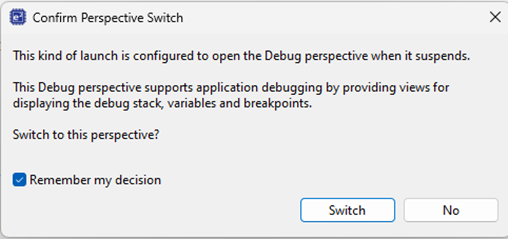
Click Allow access if you get a warning from Windows Defender. Check the Remember my decision check box and click Switch if the following dialog appears.
-
Click the Resume button twice. The program will now running. Turn the toggle ON. The motor should begin running.
Never stop the debugger while the motor is running. This will cause commutation to stop, interrupting MOSFET switching and likely leaving a coil energized. This will cause the motor to overheat and eventually burn out. If the motor is not spinning at this stage, check the connections and review the material above.
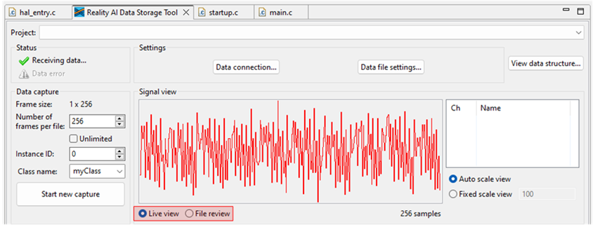
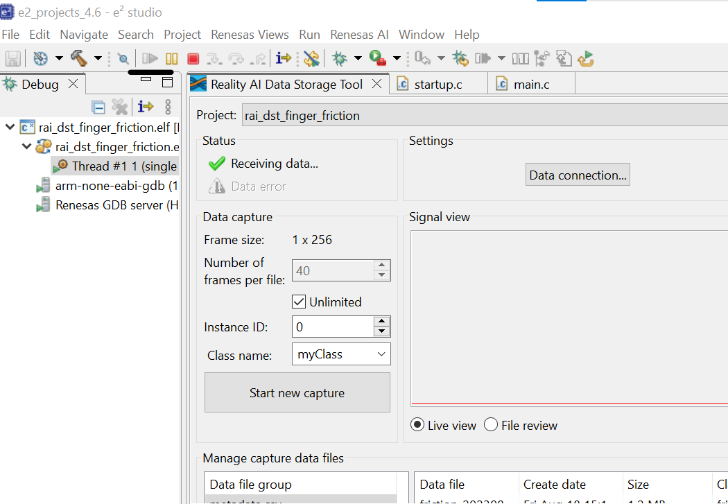
- Click the Reality AI Data Storage Tool to view and verify the waveform in the Signal view.
- If it is absent, click File review and then Live view.
- If still absent, recheck the prerequisite steps to make sure the connections are correct.
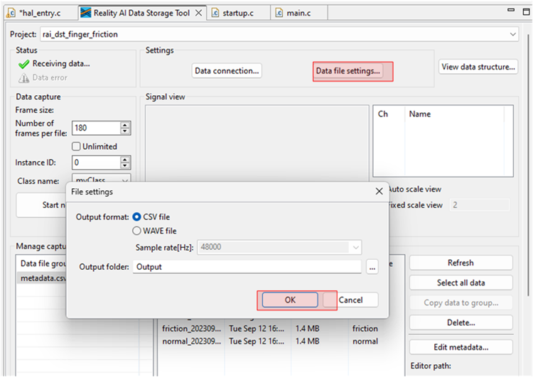
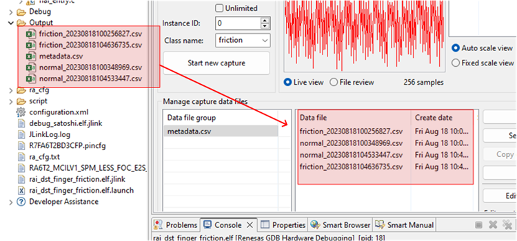
- Click Data file settings.
- Verify the CVS file and Output folder. The Output folder is relative to the project.
- Click OK to close the dialog.
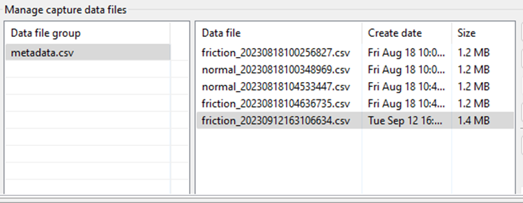
The Data Storage tool reflects the data in the project's Output folder. The data currently there was collected during the tutorial development and includes date and time information. New data will be collected in the following sections.
There are two methods to collect data: Number of frames per file and Unlimited.
- If the user selects Unlimited (by checking the Unlimited checkbox) data collection will occur until the user manually stops the collection process.
- Otherwise (Unlimited box unchecked) the collection will automatically stop once the Number of frames per file is reached.
- For this project, setting the Number of frames per file to 200 results in approximately 52 seconds of data. The remainder of this tutorial assumes Unlimited capture.
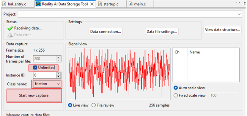
- In the Reality AI Data Storage Tool,
- Check the Unlimited checkbox.
- Enter the Class name friction.
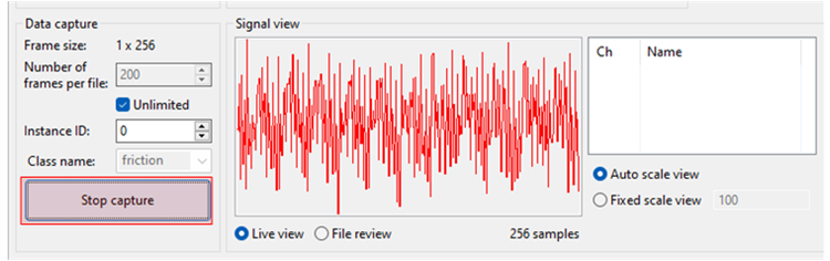
- While applying and maintaining slight friction to the motor shaft, click the Start new capture button. The button text will change to Stop Capture.
- Maintain friction for 45 to 60 seconds.
- After 45 to 60 second's elapses, click the Stop Capture button.
A new data file appears in the output folder
- Change the Class name to normal and repeat the above steps without applying friction.
This concludes the data capture portion.
-
Turn the toggle OFF to stop the motor. Click the red square icon to terminate the debug session. (If you do not see the terminate icon, select the Debug perspective in the upper right corner)
-
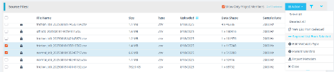
Follow these steps to upload the data files collected in the last section:
- Press and hold Ctrl, then click to select both data files.
- Scroll down to locate the Upload button.
- Click Upload.
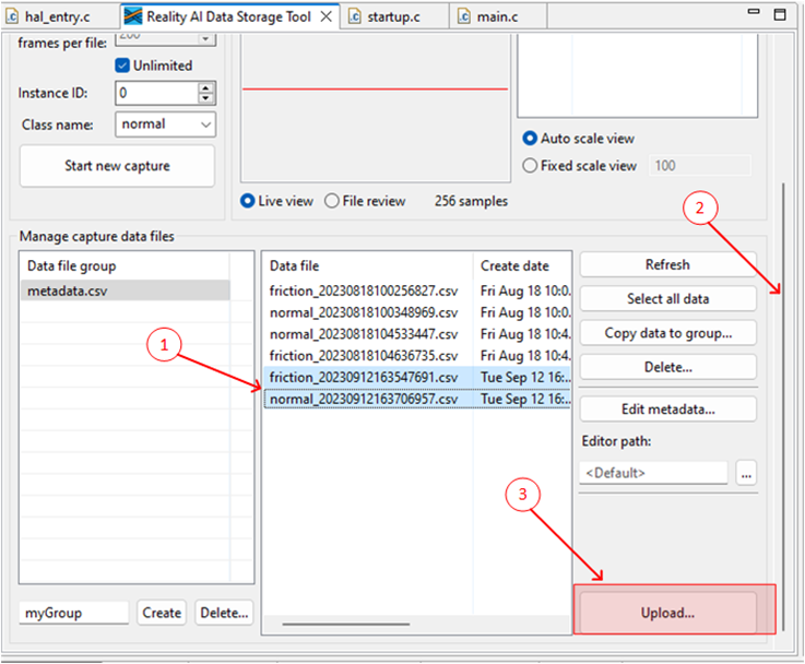
A dialog box appears, displaying the projects currently defined on the Reality AI Tools.
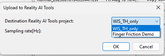
- In the dialog box:
- Select the Finger Friction Demo (or the project named you assigned earlier).
- Set the Sampling rate to
1000. - Press OK.
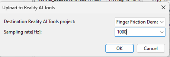
The data files, along with the metadata.csv file are uploaded. A confirmation dialog appears upon successful upload.
Section 3: Creating Models
This section covers creating AI models on the collected dataset. A Reality AI Tools account is required.
-
If you are not already logged in to Reality AI Tools, use this link with the provided password. Reach out to Renesas - Reality AI team members for credentials + instructions documents for the portal if needed.
-
Format the data. Click on the Finger Friction Demo project to set active.
-
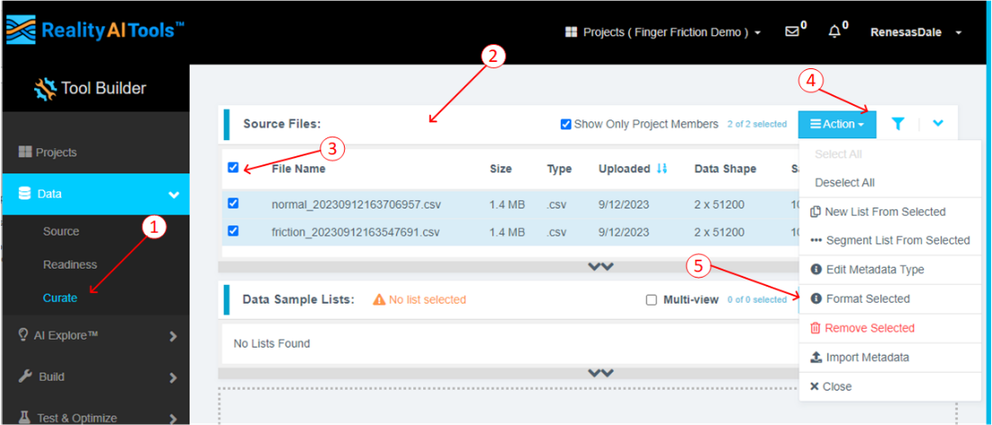
Click the Data tab on the left to expand and follow these steps:
- Click Curate.
- Click Source Files to expand.
- Check box next to File Name to select all files.
- Click the Action button.
- Click Format Selected
-
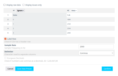
This opens a dialog box. Follow these steps:
- Click Data to expand the drop down
- Use the scroll bar to scroll down (or mouse wheel)
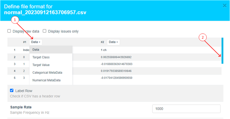
-
Select Ignore (this column is not part of the data)
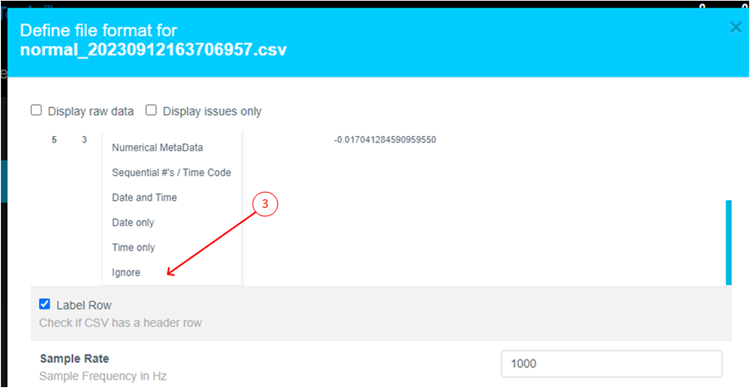
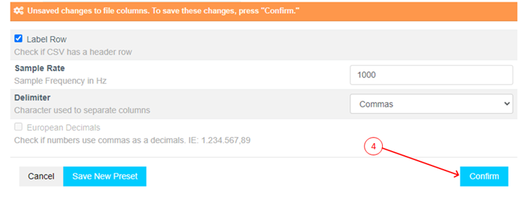
-
Click Confirm.
-
Verify that the data shape is now
1 X (num of samples)and the Sample rate is1000 Hz.
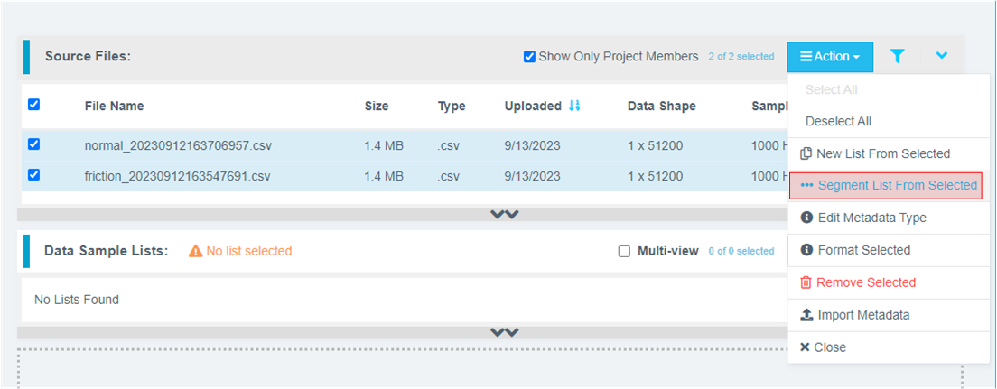
-
Preprocess/segment the data files. Click the Action button and select *** Segment List from Selected
Why Segmentation? One of the main purposes of generating models from Tools is to deploy them to a variety of Renesas MCUs. To that effect, these models must process live data within a resource constrained environment. So, for practical purposes, a model might be looking at 1 second, 500 ms, or even a smaller window length to make quick predictions on Realtime data. As opposed to a few seconds (or minutes or hours) long data stream. To mimic that effect, we break down the raw training data and feed that to the model generation engine to start learning what it is going to see in a live (production) setting.
- Assign window length, overlap, and provide name to the list using the following steps:
- Set Window Length to 256.
- Click the 50% button to select a 50% offset
- Give the list a meaningful name
- Click Submit
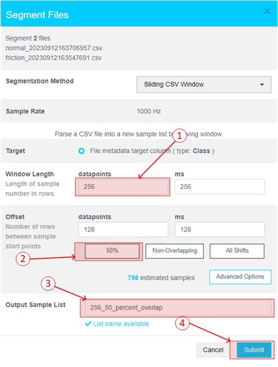
The number of estimated samples will be dependent on the amount of data collected. So, if your estimated samples do not match the following screenshot, it is still okay.
Window Length: The window length determines how much data will be considered by the AI to decide on a classification.
Offset: The offset determines how far ahead from the start of the last window the parser moves before creating a new window.
General Guide: 50% Overlap is usually a good compromise between covering starting-point variations in the data and too much redundancy.
Use non-overlapping windows when you have a great deal of data, with longer offsets. Typically, users will do initial exploration and training on a subset of the available data.
Use All Shifts (offset = 1) for testing after you have a suitable candidate classifier, and you want to simulate performance on a stream of new data arbitrarily sampled.
- After successfully creating the segmented list, navigate to AI Explore > Classes.
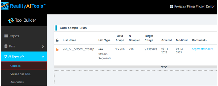
Reality AI Tools has options for creating 3 types of AI Models:
Classes: When there is labeled categorical data (option used in the tutorial). You might have noticed that we uploaded perfectly labeled data in section 1. This is needed for classification models as supervised learning is being performed.
Values: When discrete int or float values are used instead of categories. (Example: What is the exact temperature of a machine? Or What is the exact value of tire pressure of a car?). This is also supervised learning.
Anomalies: This is an anomaly detection module. It is a semi-supervised model where the user only needs examples of Normal data to create a baseline model.
-
Click the newly created list and then click Start Exploring to start the feature discovery and model training process.
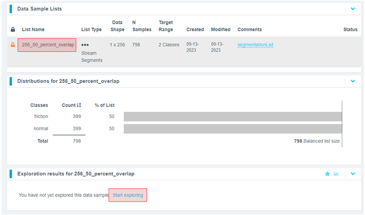
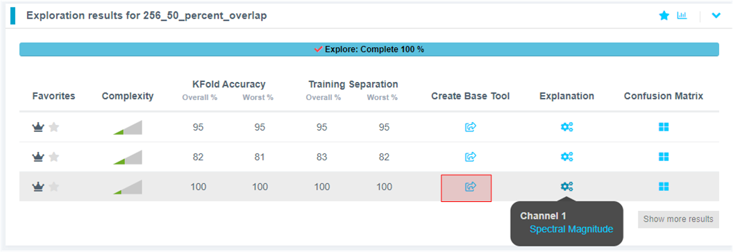
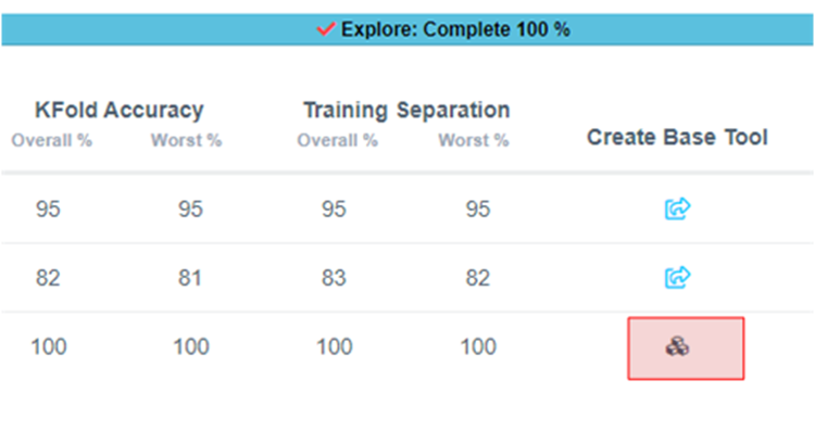
-
Once the explore finishes, select the highest performing model (we recommend model with feature space: Spectral Magnitude) and click the Create BBase Tool button. Hover over each Explanation to get more information about the model.
What is Happening in the Background
Clicking on the Start Explore button will turn the Reality AI algorithm loose on your data. It will create several optimized feature sets and machine learning models that best fit the classification problem and then summarize each model's accuracy and resource consumption.
What is the algorithm doing: AI Explore first creates a balanced subset of the sample list (meaning a list in which each class has equal numbers). If the sample list is exceptionally large, it may also sub-sample for a shorter processing time. Explore then runs through a procedure in which the Reality AI algorithms attempt to discover the best possible set of features and machine learning parameters for separating the different training classes represented in the data. The feature sets that are most promising are then used to construct machine learning models, which are trained on the sub-sample and put through a K-Fold validation.
Only the best performing results are displayed. Several hundred different feature sets and machine learning models are compared in a typical AI Explore run.
What is K-Fold validation:
K-Fold is where a given data set is split into a K number of sections/folds where each fold is used as a testing set at some point. Let us take the scenario of 10-Fold cross validation(K=10). Here, the data set is split into 10 folds. In the first iteration, the first fold is used to test the model and the rest are used to train the model. In the second iteration, the 2nd fold is used as the testing set while the rest serves as the training set. This process is repeated until each fold of the 10 folds has been used as the testing set. We use K=10 in the AI Explore page.
-
Provide a name or use the one suggested. Click Add.
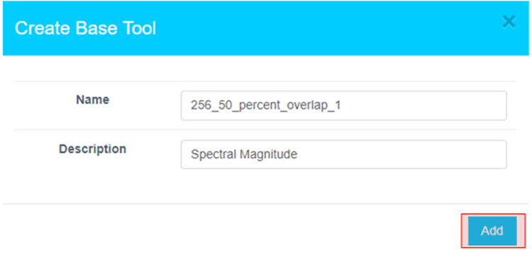
-
The icon will change, indicating the Base Tool has been created.
-
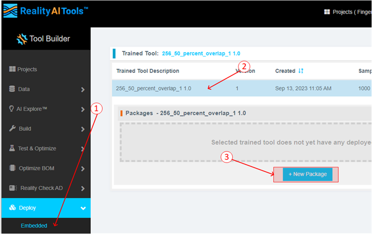
Now that the model is ready to be deployed, Follow these steps to produce a new package.
- Click Deploy > Embedded.
- Click the Trained Tool Description list.
- Click + New Package.
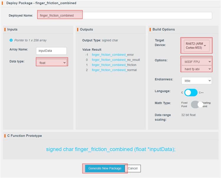
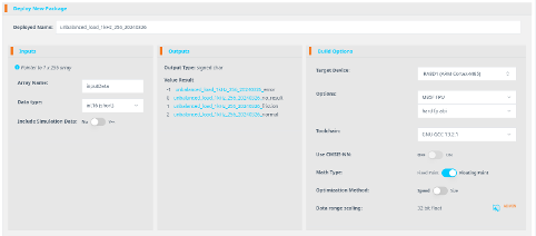
-
Set the options as indicated. The deployed name should be finger_friction_combined to match the code in e² Studio. Choosing another name will require additional edits to the code. The package will take a few minutes to generate.
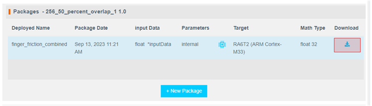
-
It will take ~10-15 minutes for the model to be available for download. Once ready, download the zip file using the highlighted button.
-
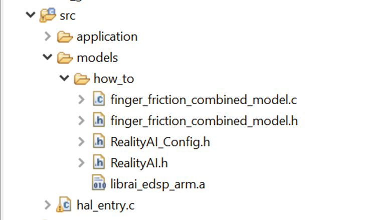
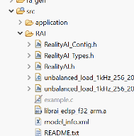
There are 7 files in the downloaded archive. Copy and paste all files except example_main.c and readme.txt to the src directory of the e² Studio project workspace (src > models > how_to or src > realityai), overwriting the current files.
File names may be different depending on the project name assigned in tools. In the files below, the model function call is specified in finger_friction_combined_model.h. If you have MCK_Workshop_Finger_Friction_Detection project, then the model is named finger_friction_workshop_model. Either is fine to test and replace.
Section 4: Deploying the model
This section covers testing the model on hardware.
-
If using project:
rai_dst_finger_friction: Open hal_entry.c and import the header file. If the deployed model name was finger_friction_combined then no changes are required. Otherwise, edit the #include to the deployed model's header file. If using the other project, edit line #7 in predict.c.
 -
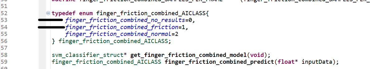
If using project:
rai_dst_finger_friction: Modify the following lines of code if the deployed model name was other thanfinger_friction_combined. Values can be found in the header file included in the last step. Edit lines by copying the class names from header file included above. Again, no edits are necessary if the deployed model name is finger_friction_combined.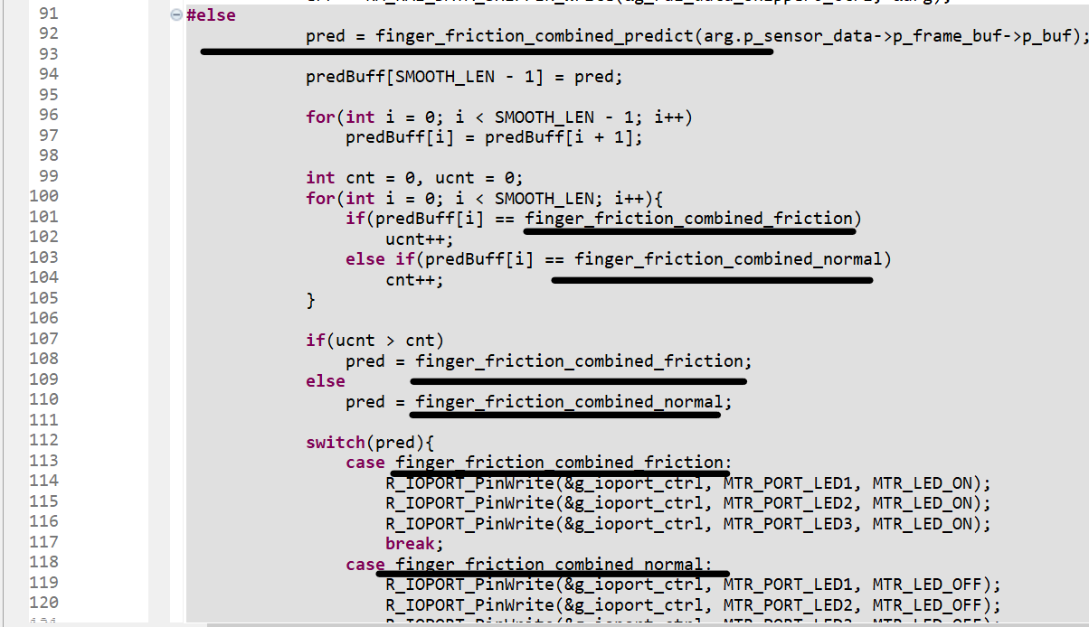
 If using the other project: all the above changes are again confined with predict.c file only.
 -
If using project:
rai_dst_finger_friction: Change the USE_SHIPPER define to 0. This will cause the project to build in the test mode.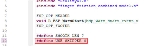 If using the other project, make the change to line
 #8indcds.c. -
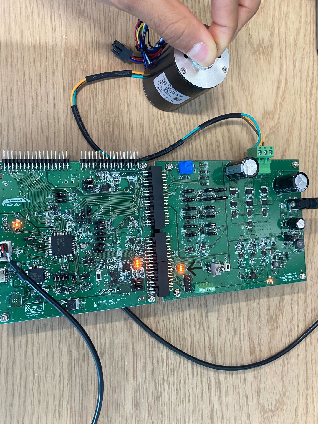
Build and debug the project as before. Click the Resume button twice. Now the board is running on inference mode. Turn the motor switch ON and run the motor.
-
Let the motor run in normal/balanced mode with no friction. The three LED's will be OFF (indicated by the arrow) during this time.
-
Apply minor/light friction. The LED's should turn on (indicated by the arrow) to indicated friction/unbalanced behavior.
Be sure to turn the toggle switch off before stopping the debugger.
Section 5: Appendix
If the Reality AI items do not appear in the title bar, perform the following steps.
- Click Help > Install Renesas IDE Features…
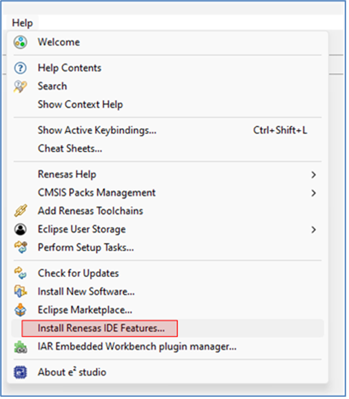
- Select the Reality AI features and click Finish.
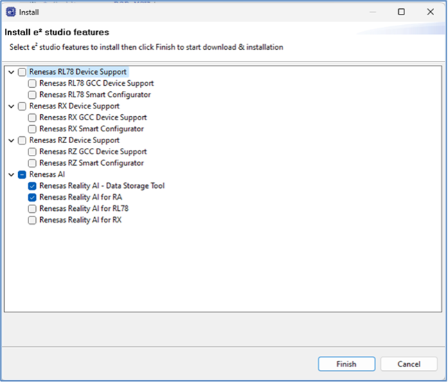
- Restart e2 studio IDE when prompted.
Introduction - RA8T1
This tutorial covers the development and testing of the Finger Friction Demo, an AI model that can detect when friction is applied to a motor shaft using only vibration data, using the Renesas RA8T1 Flexible Motor Control Kit and the Reality AI Tools portal. The Reality AI Tools portal enables the generation of AI models for non-visual sensing applications.
Objectives
This tutorial aims to provide hands-on experience in developing a simple AI demo using the Renesas RA8T1 motor kit and Reality AI Tools.
Section 1: Prerequisites
This section lists the prerequisites for running the Finger Friction demo.
Hardware and software requirements
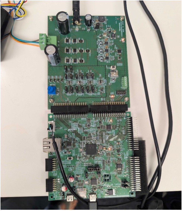
Kit required: MCK Flexible Motor Control Kit (MCK-RA8T1)
The MCK-RA8T1 is a development kit that enables easy evaluation of motor control using permanent magnet synchronous motors (brushless DC motors). With this product and the sample code and QE for Motor that can be downloaded from the website, you can start evaluating motor control using the RA8T1 right away.
For this tutorial, the inverter board needs to be positioned on INV2, not INV1.
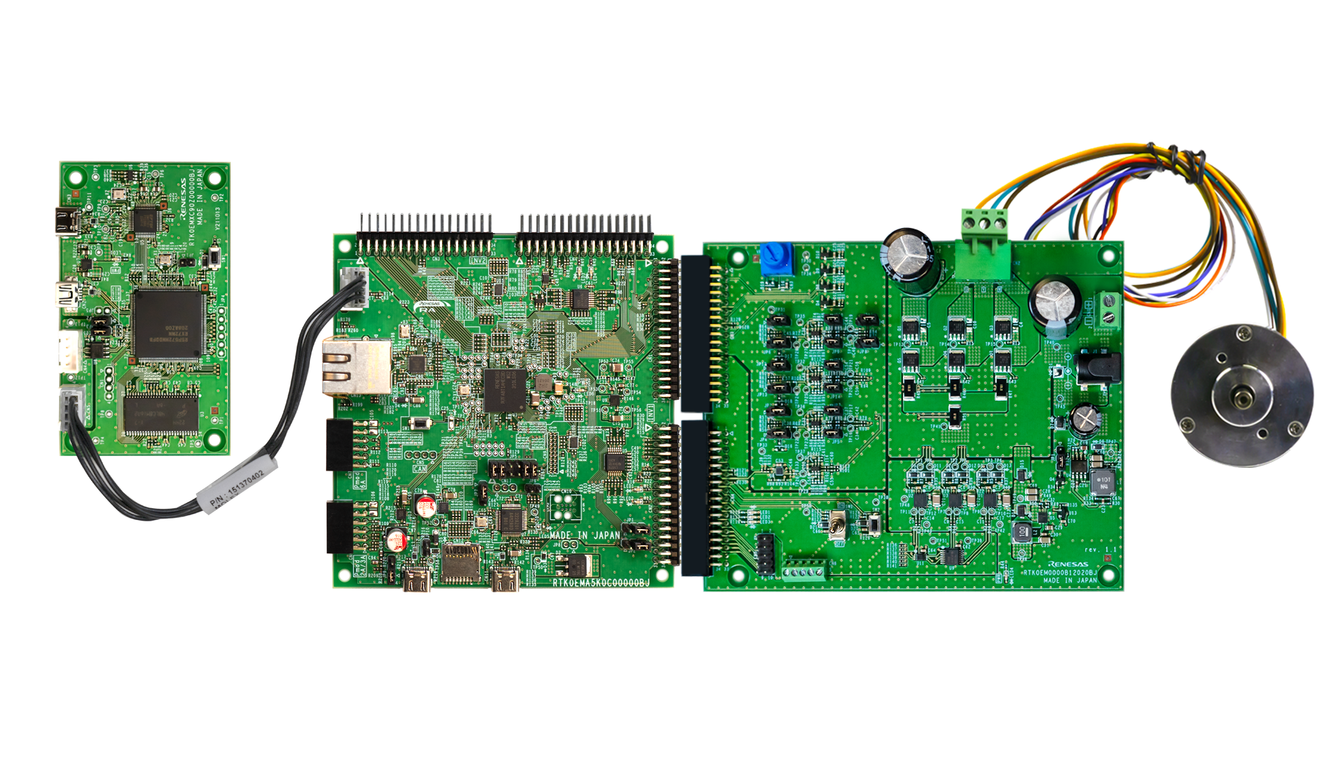
Kit contents:
- RA8T1 motor control board and low-voltage inverter
- DC brushless motor (Moon's Industries)
- Communications board (not used in this tutorial)
- USB-C to USB-A cable
Additional components:
- 24 V power supply (Recommended. Click to access similar product link)
- USB-to-UART cable (Required. Click to access similar product link)
Software Required:
- PC with Windows® 10 or 11
- Project files provided by the Renesas — Reality AI team
- Renesas e² studio IDE 2025-4.1 or newer with FSP 6.0 or newer
- Reality AI Tools account
Kit assembly
Follow these steps to assemble the kit:
Ensure SW1 is OFF and all jumpers are at default.
- Attach the standoffs and fasteners to the corners of each board.
- Connect the invertor board to the motor control board on the [INV2] connector.
- Verify whether the motor switch [SW1] is in the OFF position.
- Connect the PC to USB-C on the board.
- Connect the external power supply (optional if using RA6T2).
- Connect the USB to UART cable on to CN8 (see table below for UART to USB pin connections).
- Connect the motor to CN2.
UART Pin Reference
| Pin | Signal | Wire |
|---|---|---|
| 1 | GND to GND | Black |
| 2 | RX to TX | White |
| 3 | TX to RX | Green |
| 4 | VCC (NC) | No connection |

This tutorial requires Renesas e² studio IDE 2025-04.1 or later. Reality AI Utilities are not compatible with the existing project because it targets FSP 5.1. To use Reality AI Utilities, update the project to a newer FSP version.
- Create a Reality AI Tools account.
- Login to Reality AI Tools using the username and password provided.
Contact Renesas for account credentials and access documentation, if needed.
10. Leave the Reality AI Tools browser window open in the background.
Section 2: Data Collection
This section describes how to collect data using the Reality AI Eclipse plugin in e² Studio.
- Open e² Studio IDE and select a workspace (e.g.,
C:Renesas\RA\e2studio_v2025-04_fsp_v6.0.0_Workspace).
This tutorial assumes the above workspace path, but any location is acceptable.
-
Navigate to File > Import.
-
Select General > Existing Projects into Workspace.
-
Click Next to continue.
-
Select the Select archive file radio button and navigate to the zip file for this tutorial. Ensure the project is selected and click Finish.
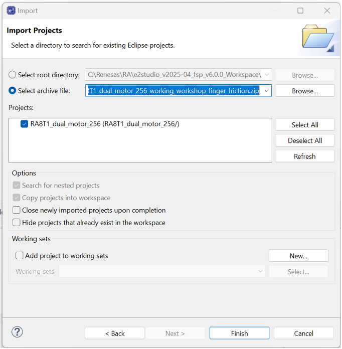
The demo project is imported into the workspace.
6. In the Reality AI Tools portal:
i. Click +Add Project.
ii. Enter a name and optional description.
iii. Click the +Add Project button in the lower right corner.
If you have explorer subscription, use the existing MCK workshop: Finger Friction Detection project available in your account to upload and analyze the data.
-
To retrieve the API key, click your username on the top-right of the screen and select API Key option.
-
Copy this API key to the clipboard. This key will be used to connect e² Studio IDE and Reality AI Tools.
-
In e² Studio and navigate to Renesas AI > Reality AI Authentication.
If Renesas AI does not appear in the menu, consult the appendix section.
-
Paste the API key and click OK. To verify this, click Test Connection. Once confirmed, click Apply and Close. The IDE can now connect to the Reality AI site.
-
Navigate to Renesas AI > Reality AI > Reality AI Utilities > Data Storage Tool. A new window will open in the bottom pane. Drag the new view to the main area for better visibility.
-
A new view opens in the bottom pane. Drag this view to the main editor area by clicking its tab and dropping it into the main view. In the view, select your project from the dropdown and choose Data File Settings…. Set Output folder to Output. This creates the default Output folder at the project root.
-
Select the project from the drop-down list and then click the Data Connection button.
-
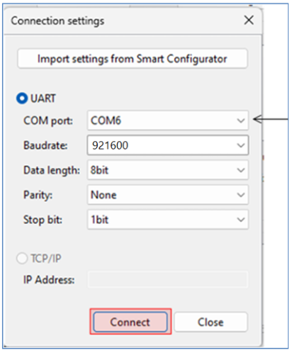
In the Connection settings dialog:
- Select the COM port,
- Set the Baud rate to
921600 - Use the communication protocol parameters
8bit-None-1bit. - Click Connect and then Close.
- Once connected, the status (top left) should show "Receiving data..." with a check mark.
A green check mark at the top-left indicates a successful connection—not necessarily that data is being received.
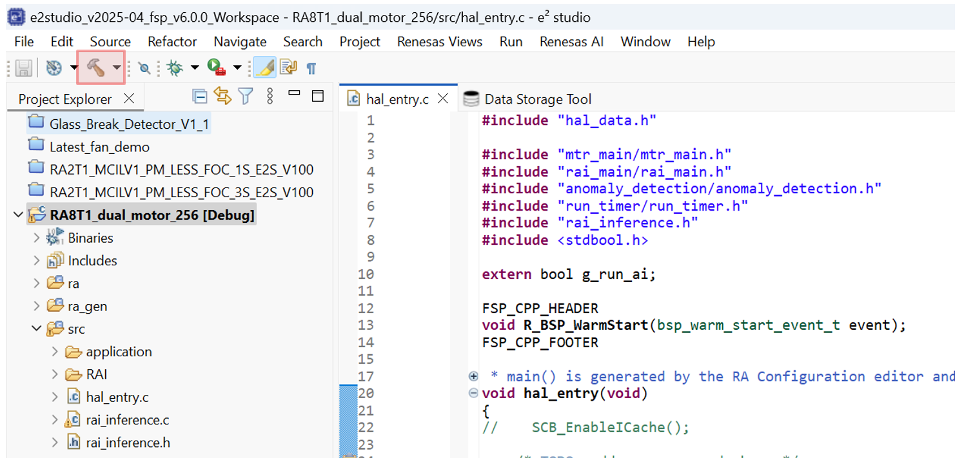
- Expand the project in the Project Explorer view and open
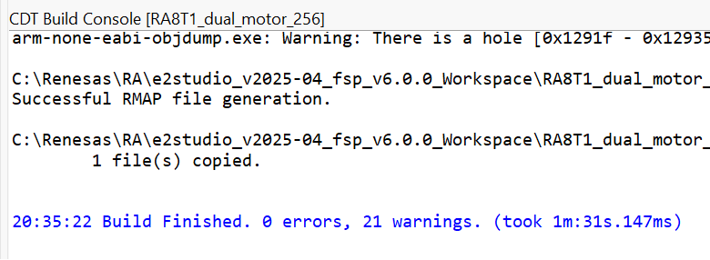
hal_entry.cin the src folder. - Build the project by clicking the hammer icon. The project should build without error. Warnings may appear; they are expected.
-
Ensure the toggle switch [SW1] is OFF. Start a debug session by clicking the Debug icon in the toolbar.
-
Click Allow access if you get a warning from Windows Defender. Check the Remember my decision check box and click Switch if the following dialog appears.
-
Click the Resume button twice. The program will now running. Turn the toggle ON. The motor should begin running.
Switch SW1 to the ON position. The motor should start running. If it does not, verify the wiring and review the previous setup steps. Use SW2 to reset the motor if the control algorithm loses closed-loop stability due to user interaction.
Never stop the debugger while the motor is running. This will cause commutation to stop, interrupting MOSFET switching and likely leaving a coil energized. This will cause the motor to overheat and eventually burn out. If the motor is not spinning at this stage, check the connections and review the material above.
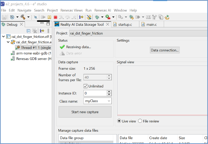
- Click the Reality AI Data Storage Tool to view and verify the waveform in the Signal view.
- If it is absent, click File review and then Live view.
- If still absent, recheck the prerequisite steps to make sure the connections are correct.
- Click Data file settings.
- Verify the CVS file and Output folder. The Output folder is relative to the project.
- Click OK to close the dialog.
The Data Storage tool reflects the data in the project's Output folder. The data currently there was collected during the tutorial development and includes date and time information. New data will be collected in the following sections.
There are two methods to collect data: Number of frames per file and Unlimited.
- If the user selects Unlimited (by checking the Unlimited checkbox) data collection will occur until the user manually stops the collection process.
- Otherwise (Unlimited box unchecked) the collection will automatically stop once the Number of frames per file is reached.
- For this project, setting the Number of frames per file to 240 results in approximately 30 seconds of data. The remainder of this tutorial assumes Unlimited capture.
- In the Reality AI Data Storage Tool,
- Check the Unlimited checkbox.
- Enter the Class name friction.
- While applying and maintaining slight friction to the motor shaft, click the Start new capture button. The button text will change to Stop Capture.
- Maintain friction for 45 to 60 seconds.
- After 45 to 60 second's elapses, click the Stop Capture button.
A new data file appears in the output folder
- Change the Class name to normal and repeat the above steps without applying friction.
This concludes the data capture portion.
-
Turn the toggle OFF to stop the motor. Click the red square icon to terminate the debug session. (If you do not see the terminate icon, select the Debug perspective in the upper right corner)
-
Follow these steps to upload the data files collected in the last section:
- Press and hold Ctrl, then click to select both data files.
- Scroll down to locate the Upload button.
- Click Upload.
A dialog box appears, displaying the projects currently defined on the Reality AI Tools.
- In the dialog box:
- Select the Finger Friction Demo (or the project named you assigned earlier).
- Set the Sampling rate to
1000. - Press OK.
The data files, along with the metadata.csv file are uploaded. A confirmation dialog appears upon successful upload.
Section 3: Creating Models
This section covers creating AI models on the collected dataset. A Reality AI Tools account is required.
-
If you are not already logged in to Reality AI Tools, use this link with the provided password. Reach out to Renesas - Reality AI team members for credentials + instructions documents for the portal if needed.
-
Format the data. Click on the Finger Friction Demo project to set active.
-
Click the Data tab on the left to expand and follow these steps:
- Click Curate.
- Click Source Files to expand.
- Check box next to File Name to select all files.
- Click the Action button.
- Click Format Selected
-
This opens a dialog box. Follow these steps:
- Click Data to expand the drop down
- Use the scroll bar to scroll down (or mouse wheel)
-
Select Ignore (this column is not part of the data)
-
Click Confirm.
-
Verify that the data shape is now
1 X (num of samples)and the Sample rate is2000 Hz.
-
Preprocess/segment the data files. Click the Action button and select *** Segment List from Selected
Why Segmentation? One of the main purposes of generating models from Tools is to deploy them to a variety of Renesas MCUs. To that effect, these models must process live data within a resource constrained environment. So, for practical purposes, a model might be looking at 1 second, 500 ms, or even a smaller window length to make quick predictions on Realtime data. As opposed to a few seconds (or minutes or hours) long data stream. To mimic that effect, we break down the raw training data and feed that to the model generation engine to start learning what it is going to see in a live (production) setting.
- Assign window length, overlap, and provide name to the list using the following steps:
- Set Window Length to 256.
- Click the 50% button to select a 50% offset
- Give the list a meaningful name
- Click Submit
The number of estimated samples will be dependent on the amount of data collected. So, if your estimated samples do not match the following screenshot, it is still okay.
Window Length: The window length determines how much data will be considered by the AI to decide on a classification.
Offset: The offset determines how far ahead from the start of the last window the parser moves before creating a new window.
General Guide: 50% Overlap is usually a good compromise between covering starting-point variations in the data and too much redundancy.
Use non-overlapping windows when you have a great deal of data, with longer offsets. Typically, users will do initial exploration and training on a subset of the available data.
Use All Shifts (offset = 1) for testing after you have a suitable candidate classifier, and you want to simulate performance on a stream of new data arbitrarily sampled.
- After successfully creating the segmented list, navigate to AI Explore > Classes.
Reality AI Tools has options for creating 3 types of AI Models:
Classes: When there is labeled categorical data (option used in the tutorial). You might have noticed that we uploaded perfectly labeled data in section 1. This is needed for classification models as supervised learning is being performed.
Values: When discrete int or float values are used instead of categories. (Example: What is the exact temperature of a machine? Or What is the exact value of tire pressure of a car?). This is also supervised learning.
Anomalies: This is an anomaly detection module. It is a semi-supervised model where the user only needs examples of Normal data to create a baseline model.
-
Click the newly created list and then click Start Exploring to start the feature discovery and model training process.
-
Once the explore finishes, select the highest performing model (we recommend model with feature space: Spectral Magnitude) and click the Create BBase Tool button. Hover over each Explanation to get more information about the model.
What is Happening in the Background
Clicking on the Start Explore button will turn the Reality AI algorithm loose on your data. It will create several optimized feature sets and machine learning models that best fit the classification problem and then summarize each model's accuracy and resource consumption.
What is the algorithm doing: AI Explore first creates a balanced subset of the sample list (meaning a list in which each class has equal numbers). If the sample list is exceptionally large, it may also sub-sample for a shorter processing time. Explore then runs through a procedure in which the Reality AI algorithms attempt to discover the best possible set of features and machine learning parameters for separating the different training classes represented in the data. The feature sets that are most promising are then used to construct machine learning models, which are trained on the sub-sample and put through a K-Fold validation.
Only the best performing results are displayed. Several hundred different feature sets and machine learning models are compared in a typical AI Explore run.
What is K-Fold validation:
K-Fold is where a given data set is split into a K number of sections/folds where each fold is used as a testing set at some point. Let us take the scenario of 10-Fold cross validation(K=10). Here, the data set is split into 10 folds. In the first iteration, the first fold is used to test the model and the rest are used to train the model. In the second iteration, the 2nd fold is used as the testing set while the rest serves as the training set. This process is repeated until each fold of the 10 folds has been used as the testing set. We use K=10 in the AI Explore page.
-
Provide a name or use the one suggested. Click Add.
-
The icon will change, indicating the Base Tool has been created.
-
Now that the model is ready to be deployed, Follow these steps to produce a new package.
- Click Deploy > Embedded.
- Click the Trained Tool Description list.
- Click + New Package.
-
Set the options as indicated. The deployed name should be unbalanced_load_1kHz_256_20240326 to match the code in e² Studio. Choosing another name will require additional edits to the code. The package will take a few minutes to generate.
-
It will take ~10-15 minutes for the model to be available for download. Once ready, download the zip file using the highlighted button.
-
The downloaded archive contains nine files. Copy all files except
example_main.candreadme.txtinto the project workspace at:src > RAIWhen prompted, overwrite the existing files.
::: info Note
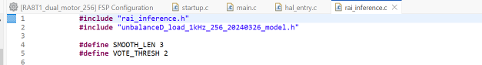
File names may vary depending on the project name assigned in tools. The model function call used in this project is defined in unbalanced_load_1khz_256_20240326_model.h
:::
Section 4: Deploying the model
This section covers testing the model on hardware.
-
Open hal_entry.c and import the header file. If the deployed model name was finger_friction_combined then no changes are required. Otherwise, edit the #include to the deployed model's header file.
-
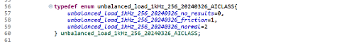
Modify the following lines of code: #39, #44, #46 & #48 if the deployed model name was other than unbalanced_load_1khz_256_20240326. Values can be found in the header file.
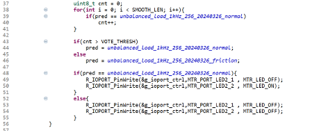
Edit lines above by copying the class names from header file included above. No edits are necessary if the deployed model name is unbalanced_load_1khz_256_20240326.
-
Build and debug the project as before. Click the Resume button twice. Now the board is running on inference mode. Turn the motor switch ON and run the motor.
-
Let the motor run in normal/balanced mode with no friction. The second LED will be ON during this time.
-
Apply friction similar to your data collection process. The LED’s should turn OFF to indicate friction/ unbalanced behavior.
Be sure to turn the toggle switch off before stopping the debugger.
Section 5: Appendix
If the Reality AI items do not appear in the title bar, perform the following steps.
- Click Help > Install Renesas IDE Features…
- Select the Reality AI features and click Finish.
- Restart e2 studio IDE when prompted.