Creating/Importing a Project
This section describes how to create a project with VK-RA6E1 to explore various options in the Utilities plugins. The VK (Voice Kit) board comes with a microphone for data collection. Ideally, you need some sensor connected to various Renesas RA MCUs/Boards to collect data and test machine learning models.
The example project is for illustration purposes only. You can recreate the same steps with other boards/MCUs in the RA series. This user manual also comes with a fully set up example project that you can reference.
Create a New Project
-
On the top navigation menu, click File > New.
-
Go to File > New and select Renesas C/C++ Project, then Renesas RA.
-
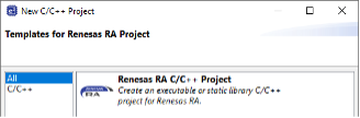
In the new project wizard window, select Renesas RA C/C++ Project and click Next.
-
Specify a project name and click Next.
-
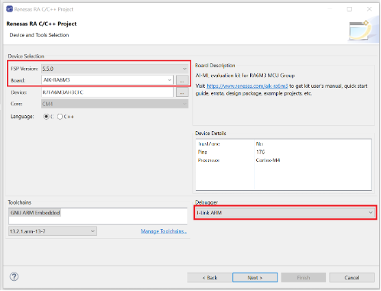
Select the FSP version matching your BSP and FSP installation (e.g., 5.5.0) and set the Board to the one you are connecting. In the example below, we are using AIK-RA6M3. Verify that the Debugger is set to JLink ARM and click Next.
-
On the next window, leave Executable and No RTOS selected. Click Next.
-
Once the new project is created, e² Studio will switch to a layout optimized for developing Renesas RA projects.
- Select the Stacks tab at the bottom of the FSP Configuration pane.
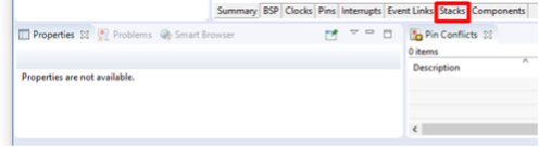
- Select the Stacks tab at the bottom of the FSP Configuration pane.
-
- Access the New Stack menu and select Connectivity > I2C Communication Device (rm_comms_i2c).
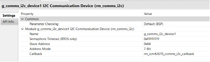
Use the Properties tab to configure the following properties for this new module:
- Access the New Stack menu and select Connectivity > I2C Communication Device (rm_comms_i2c).
I2C Communication Device Properties
| Name | Slave Address | Callback |
|---|---|---|
| g_comms_i2c_device1 | 0x68 | rm_icm42670_comms_i2c_callback |
Why rm_comms_i2c?
Middleware to implement the I2C communications interface used by the sensor. This module implements the Communications Middleware Interface.
Features:
- Reading and writing data over I2C bus
- Writes to I2C bus, then reads with restart
- Single I2C bus used by multiple devices
Configurations
Build Time Configurations for rm_comms_i2c
The following build time configurations are defined in fsp_cfg/rm_comms_i2c_cfg.h.
Build Time Configurations for rm_comms_i2c
| Configuration | Options | Default | Description |
|---|---|---|---|
| Parameter Checking | Default (BSP) / Enabled / Disabled | Default (BSP) | If selected, code for parameter checking is included in the build. |
Configurations for Connectivity > I2C Shared Bus (rm_comms_i2c)
This module can be added via New Stack > Connectivity > I2C Shared Bus (rm_comms_i2c).
Configurations for I2C Shared Bus (rm_comms_i2c)
| Configuration | Options | Default | Description |
|---|---|---|---|
| Name | Name must be a valid C symbol | g_comms_i2c_bus0 | Module name. |
| Bus Timeout | Non-negative integer ≤ 0xFFFFFFFF | 0xFFFFFFFF | Set timeout for locking bus in RTOS. |
| Semaphore for Blocking (RTOS only) | Unuse / Use | Use | Set semaphore for blocking in RTOS. |
| Recursive Mutex for Bus (RTOS only) | Unuse / Use | Use | Set mutex for locking bus in RTOS. |
| Channel | Manual Entry | 0 | IIC channel |
| Rate | Standard / Fast-mode / Fast-mode plus | Standard | Transfer rate for lower-level driver. |
Configurations for Connectivity > I2C Communication Device (rm_comms_i2c)
This module can be added via New Stack > Connectivity > I2C Communication Device (rm_comms_i2c).
Configurations for I2C Communication Device (rm_comms_i2c)
| Configuration | Options | Default | Description |
|---|---|---|---|
| Name | Valid C symbol | g_comms_i2c_device0 | Module name. |
| Semaphore Timeout (RTOS only) | Integer ≤ 0xFFFFFFFF | 0xFFFFFFFF | Set timeout for blocking in RTOS. |
| Slave Address | Non-negative integer | 0x00 | Specify the slave address. |
| Address Mode | 7-Bit / 10-Bit | 7-Bit | Select the I2C address mode. |
| Callback | Valid C symbol | comms_i2c_callback | User callback function. |
Pin Configuration:
This module uses SDA and SCL pins of I2C Master, SCI I2C, IICA Master, and SAU I2C.
- In the I2C Communication Device module, in g_comms_i2c_bus1 I2C Shared Bus (rm_comms_i2c), use the Properties tab to configure the following:
Properties for g_comms_i2c_bus1
| Name | Value |
|---|---|
| Name | g_comms_i2c_bus1 |
| Channel | 1 |
| Rate | Fast-mode |
- Add I2C Communications Peripherals
In the I2C Communication Device module, click the stack icon to Add I2C Communications peripherals, then click New and choose I2C Master (r_iic_master).
Use the Properties tab to configure the following properties for this new module.
I2C Master Properties
| Property | Value |
|---|---|
| Common > DTC on Transmission and Reception | Enabled |
| Name | g_i2c_master1 |
| Interrupt priority | 12 |
| Timeout Mode | Short Mode |
- Add DTC Driver for Transmission (Optional)
In the I2C Communication Device module, click the stack icon for Add DTC Driver for Transmission [optional], then click New and choose Transfer (r_dtc).
- Access the New Stack menu again and select: Input > External IRQ (
r_icu).
Use the Properties tab to configure the following properties for this new module.
External IRQ Properties
| Property | Value |
|---|---|
| Name | g_external_irq6_pmod1 |
| Channel | 6 |
| Trigger | Rising |
| Pin Interrupt Priority | Priority 12 |
Note: You should see pin IRQ06 update to P000 when you change Channel to 6.
Access the New Stack menu again and select Add AI > Data Shipper (rm_rai_data_shipper)
Why rm_rai_data_shipper?
This is the middleware to implement the Data Shipper for Reality AI applications.
This module implements the Data Shipper Interface.
Overview
RAI Data Shipper is mainly for sending data collected by RAI Data Collector to a PC so that it can be used for Reality AI model training.
It utilizes the Communications Middleware Interface and all communications are fully asynchronous.
The data being transported may be any combination of the following:
- Sensor data
- System events/errors
- Debug data and diagnostic information (including RAI runtime output)
Sensor data is provided by a Data Collector instance via the data ready callback.
System events and debug data are prepared by the application.
A callback is used to notify the application when communication is finished.
Sensor data buffers must be released if they are not used.
An error flag will be set if there is any error during data transmission.
Features
- Supports up to 8 Data Collector instances.
- Supports the following interfaces:
RM_COMMS_UARTwith/without CRC-8RM_COMMS_USB_PCDCwith/without CRC-8
Configurations
Defined in fsp_cfg/rm_rai_data_shipper_cfg.h.
Build Time Configurations for rm_rai_data_shipper
| Configuration | Options | Default | Description |
|---|---|---|---|
| Parameter Checking | Default (BSP) | Enabled | Disabled | Default (BSP) | If selected, code for parameter checking is included in the build. |
| Max Number Of DC Instances | Positive integer (1–8) | 8 | Maximum number of DC instances to send. |
Configurations for AI > Data Shipper (rm_rai_data_shipper)
This module can be added to the Stacks tab via: New Stack > AI > Data Shipper (rm_rai_data_shipper).
Configurations for AI > Data Shipper
| Configuration | Options | Default | Description |
|---|---|---|---|
| Name | Valid C symbol | g_rai_data_shipper0 | Module name |
| Frame Rate Divider | Non-negative value | 0 | Skip write requests |
| Callback | Valid C symbol | rai_data_shipper0_callback | User callback function on data sent or error |
Clock Configuration
This module has no required clock configurations.
Pin Configuration
This module does not use I/O pins.
Limitations
- Two-way communication is not supported — data is always sent from device to host.
- Users must avoid race conditions when using multiple data collector instances.
- To use
RM_COMMS_USB_PCDCwith Full Speed mode and DMA, frame buffer length must be a multiple of 2 when an 8-bit channel is used. - To use
RM_COMMS_USB_PCDCwith High Speed mode and DMA:- Frame buffer length must be a multiple of 2 for 16-bit channel.
- For 8-bit channel, frame buffer length must be a multiple of 4.
- RAI Data Collector (snapshot mode) and
RM_COMMS_USB_PCDCmust use different timers — they operate independently.
- Access
g_rai_data_collector0
Use the Properties tab to configure the following properties for this new module.
Data Collector (g_rai_data_collector0) Properties
| Property | Value |
|---|---|
| General > Frame Buffer Length | 512 |
| Data Feed Mode > Channels | 3 |
| Data Feed Mode > Channels 0–2 | Set Channels 0, 1, and 2 Data Type to Single Float |
Why g_rai_data_collector?
Middleware to implement the Data Collector for Reality AI applications. This module implements the Data Collector Interface.
Overview
Data Collector abstracts the collection of data from sensors so that data samples are accumulated into fixed-length frames before being made available to the application. Support of snapshot mode and data feed mode are required to accommodate background and cooperative data collection. Each mode supports up to 8 sensor channels. Each sensor channel will be captured into a separate frame buffer. Frame buffers shall have the same amount of data samples, however, data type can be different (int32_t, float, uint8_t, etc.). Users must ensure frame buffers will be filled at the same rate.
When all frame buffers are filled, they will be provided to the application via data ready callback. After they are consumed, the application must release them by calling RM_RAI_DATA_COLLECTOR_BufferRelease(). For seamless operation, PING-PONG buffers will be used. Ideally, buffers are released before the other set of buffers are filled. However, frame buffer overrun can occur if the application takes longer to process the data. If it happens, the application is notified with a buffer-overrun event via the error callback. No user intervention is required; buffer overrun will disappear when frame buffers are released. If not all sensor channels are configured to work at the same pace, the application will get a buffer-out-of-sync error. Users must reconfigure sensor channels and ensure all channels work at the same pace. If sensor channels can't work at the same rate, multiple data collector instances are required.
Features
- Snapshot mode and data feed mode are supported.
- Maximally 8 sensors are supported for each mode.
- Mix mode is supported (both snapshot and data feed enabled).
Snapshot Mode
Snapshot mode periodically pulls data from user-specified sources and saves to designated frame buffers. It requires a DTC module and a timer module. DTC will work in chain mode, enabling data collection from various, potentially non-linear and different-sized sources. Timer (GPT or Asynchronous General Purpose Timer) provides activation source for DTC to work periodically. To select this activation source, relevant interrupt must be configured in the timer module. The application must start the timer to enable DTC after sensor source addresses are registered.
Data Feed Mode
Data feed mode requires the data producer to push data directly to the designated frame buffer whenever data is ready. Data can be pushed synchronously or asynchronously.
- Synchronous mode: for short data copies to the frame buffer.
- Asynchronous mode: uses DTC/DMAC for data transfer. Application must add DTC/DMAC modules and initialize transfer descriptors for asynchronous transfer.
Usage Notes
- Do not add DTC stack and timer stack to data collector instance for data feed mode.
- Users must make sure all channels of a data collector instance operate at the same pace.
- Interrupt priority level of the timer stack in the data collector instance must be higher (numerically lower) than that of RM COMMS USB PCDC GPT Overflow interrupt.
Configurations
Defined in fsp_cfg/rm_rai_data_collector_cfg.h.
Build Time Configurations for rm_rai_data_collector
| Configuration | Options | Default | Description |
|---|---|---|---|
| Parameter Checking | Default (BSP) / Enabled / Disabled | Default (BSP) | If selected, code for parameter checking is included in the build. |
| Max Number Of Channels | Positive integer ≤ 16 | 16 | Max number of channels. |
Configurations for AI > Data Collector (rm_rai_data_collector)
Add via New Stack > AI > Data Collector (rm_rai_data_collector).
Configurations for AI > Data Collector
| Category | Setting / Field | Options / Constraints | Default Value | Description |
|---|---|---|---|---|
| General | Name | Name must be a valid C symbol | g_rai_data_collector0 | Module name |
| General | ID | Positive integer | 0 | Instance ID |
| General | Frame Buffer Length | Positive integer > 0 | 100 | Length of frame buffers in data samples |
| General | Data Ready Callback | Name must be a valid C symbol | rai_data_collector0_callback | Callback function on data ready |
| General | Error Callback | Name must be a valid C symbol | rai_data_collector0_error_callback | Callback function for error events |
| Data Feed | Channel 0 Name | Valid C variable name | dc0_data_feed_ch0 | Channel name |
| Data Feed | Channel 0 Data Type | MCU-specific options | — | Channel Data Type |
| Data Feed | Channel 1 Name | Valid C variable name | dc0_data_feed_ch1 | Channel name |
| Data Feed | Channel 1 Data Type | MCU-specific options | — | Channel Data Type |
| Data Feed | Channel 2 Name | Valid C variable name | dc0_data_feed_ch2 | Channel name |
| Data Feed | Channel 2 Data Type | MCU-specific options | — | Channel Data Type |
| Data Feed | Channel 3 Name | Valid C variable name | dc0_data_feed_ch3 | Channel name |
| Data Feed | Channel 3 Data Type | MCU-specific options | — | Channel Data Type |
| Data Feed | Channel 4 Name | Valid C variable name | dc0_data_feed_ch4 | Channel name |
| Data Feed | Channel 4 Data Type | MCU-specific options | — | Channel Data Type |
| Data Feed | Channel 5 Name | Valid C variable name | dc0_data_feed_ch5 | Channel name |
| Data Feed | Channel 5 Data Type | MCU-specific options | — | Channel Data Type |
| Data Feed | Channel 6 Name | Valid C variable name | dc0_data_feed_ch6 | Channel name |
| Data Feed | Channel 6 Data Type | MCU-specific options | — | Channel Data Type |
| Data Feed | Channel 7 Name | Valid C variable name | dc0_data_feed_ch7 | Channel name |
| Data Feed | Channel 7 Data Type | MCU-specific options | — | Channel Data Type |
| Data Feed | Channels (count) | Integer between 0 and 8 | 0 | Number of Data Feed Mode channels |
| Snapshot | Snapshot Channel 0 Name | Valid C variable name | dc0_snapshot_ch0 | Channel name |
| Snapshot | Snapshot Channel 0 Data Type | MCU-specific options | — | Channel Data Type |
| Snapshot | Snapshot Channel 1 Name | Valid C variable name | dc0_snapshot_ch1 | Channel name |
| Snapshot | Snapshot Channel 1 Data Type | MCU-specific options | — | Channel Data Type |
| Snapshot | Snapshot Channel 2 Name | Valid C variable name | dc0_snapshot_ch2 | Channel name |
| Snapshot | Snapshot Channel 2 Data Type | MCU-specific options | — | Channel Data Type |
| Snapshot | Snapshot Channel 3 Name | Valid C variable name | dc0_snapshot_ch3 | Channel name |
| Snapshot | Snapshot Channel 3 Data Type | MCU-specific options | — | Channel Data Type |
| Snapshot | Snapshot Channel 4 Name | Valid C variable name | dc0_snapshot_ch4 | Channel name |
| Snapshot | Snapshot Channel 4 Data Type | MCU-specific options | — | Channel Data Type |
| Snapshot | Snapshot Channel 5 Name | Valid C variable name | dc0_snapshot_ch5 | Channel name |
| Snapshot | Snapshot Channel 5 Data Type | MCU-specific options | — | Channel Data Type |
| Snapshot | Snapshot Channel 6 Name | Valid C variable name | dc0_snapshot_ch6 | Channel name |
| Snapshot | Snapshot Channel 6 Data Type | MCU-specific options | — | Channel Data Type |
| Snapshot | Snapshot Channel 7 Name | Valid C variable name | dc0_snapshot_ch7 | Channel name |
| Snapshot | Snapshot Channel 7 Data Type | MCU-specific options | — | Channel Data Type |
| Snapshot | Channels (count) | Integer between 0 and 8 | 0 | Number of snapshot mode channels |
| Snapshot | DTC Transfer Count | Positive integer > 0 | 1 | DTC transfer count on each activation |
| Clock Config | — | — | — | This module has no required clock configurations |
| Pin Config | — | — | — | This module does not use I/O pins |
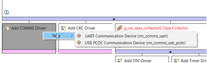
- Add COMMS Driver — USB PCDC (
rm_comms_usb_pcdc)
Under the Data Shipper module:
- Click Add COMMS Driver.
- Click New → USB PCDC Communication Device (
rm_comms_usb_pcdc).
Overview
Middleware to implement a generic communications interface over USB_PCDC. This module implements the Communications Middleware Interface.
Features
- Non-blocking API for bare metal.
- Non-blocking and blocking API for RTOS.
- Configure
g_timer0Timer (General PWM -r_gpt)
Timer g_timer0 Properties
| Property | Value |
|---|---|
| General > Period | 500 |
| General > Period Unit | Microseconds |
| Interrupts > Overflow/Crest Interrupt Priority | Priority 12 |
Why r_gpt?
Driver for the GPT32 and GPT16 peripherals on RA MCUs. This module implements the Timer Interface.
Overview
The GPT module can be used to count events, measure external input signals, generate a periodic interrupt, or output a periodic or PWM signal to a GTIOC pin.
This module supports the GPT peripherals GPT32EH, GPT32E, GPT32, and GPT16.
GPT16 is a 16-bit timer. The other peripherals (GPT32EH, GPT32E, and GPT32) are 32-bit timers. The 32-bit timers are all treated the same in this module from the API perspective.
Features
- Supports periodic mode, one-shot mode, and PWM mode.
- Supports count source of PCLK, GTETRG pins, GTIOC pins, or ELC events.
- Supports debounce filter on GTIOC pins.
- Signal can be output to a pin.
- Configurable period (counts per timer cycle).
- Configurable duty cycle in PWM mode.
- Supports runtime reconfiguration of period.
- Supports runtime reconfiguration of duty cycle in PWM mode.
- Supports runtime reconfiguration of compare match value.
- APIs are provided to start, stop, and reset the counter.
- APIs are provided to get the current period, source clock frequency, and count direction.
- APIs are provided to get the current timer status and counter value.
- Supports start, stop, clear, count up, count down, and capture by external sources from GTETRG pins, GTIOC pins, or ELC events.
- Supports symmetric and asymmetric PWM waveform generation.
- Supports one-shot synchronous pulse waveform generation.
- Supports automatic addition of dead time.
- Supports generating ELC events to start an ADC scan at a compare match value (see Event Link Controller (
r_elc)) and updating the compare match value. - Supports linking with a POEG channel to automatically disable GPT output when an error condition is detected.
- Supports setting the counter value while the timer is stopped.
- Supports enabling and disabling output pins.
- Supports skipping up to seven overflow/underflow (crest/trough) interrupts at a time.
- Supports generating custom PWM waveforms by configuring the pin's output level at each compare match and cycle end.
- Configure
r_usb_basic
r_usb_basic Properties
| Property | Value |
|---|---|
| Module > USBFS Interrupt Priority | Priority 10 |
| Module > USBFS Resume Priority | Priority 10 |
| Module > USBFS D0FIFO Interrupt Priority | Priority 10 |
| Module > USBFS D1FIFO Interrupt Priority | Priority 10 |
- Configure
g_timeout_timer2Timer (General PWM -r_gpt)
Timer g_timeout_timer2 Properties
| Property | Value |
|---|---|
| General > Name | g_timeout_timer2 |
| General > Channel | 2 |
| General > Mode | One-Shot |
| General > Period | 250 |
| General > Period Unit | Millisecond |
| Interrupts > Callback | gpt_timeout_callback |
| Interrupts > Overflow/Crest Interrupt Priority | Priority 13 |
- Configure
g_led_timer1Timer (General PWM -r_gpt)
Timer g_led_timer1 Properties
| Property | Value |
|---|---|
| General > Name | g_led_timer1 |
| General > Channel | 1 |
| General > Mode | Periodic |
| General > Period | 250 |
| General > Period Unit | Millisecond |
| Interrupts > Callback | rai_led_timer_callback |
| Interrupts > Overflow/Crest Interrupt Priority | Priority 15 |
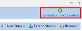
- Apply RA Configuration
RA Configuration for this section is complete. Apply changes to the project source by clicking the Generate Project Content button in the top-right corner of the Configurator window.
When prompted to Proceed with save and generate, tick the box next to Always save and generate without asking and click Proceed.
- Generate Code
The FSP Configurator will extract all the necessary drivers and generate the code based on the configuration provided in the Properties tab.
Now, you can add the required Reality AI Model files and run the project to test models and collect data.
Import an Existing Project
Use this option to load an existing project (including the example project provided with this document).
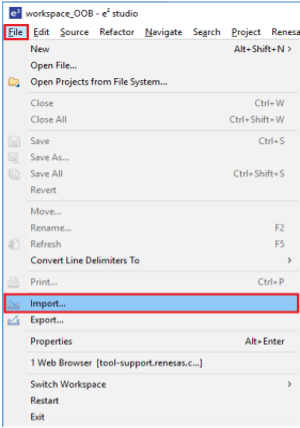
- On the top navigation menu, click File > Import.
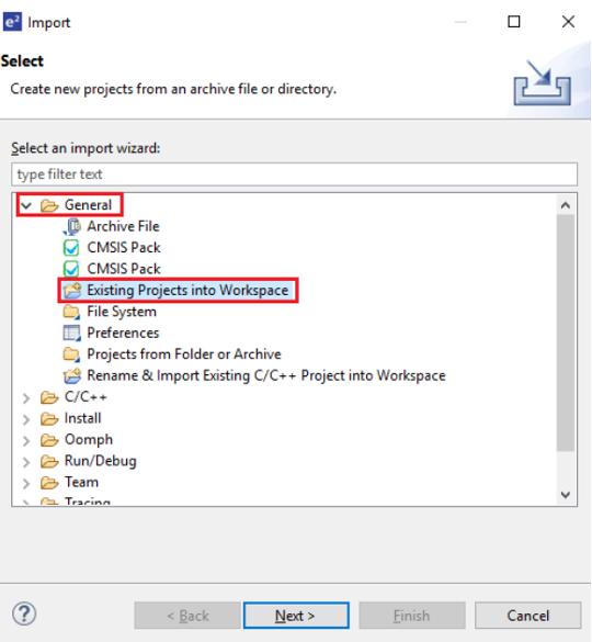
- In the Import dialog box, select General > Existing Projects into Workspace.
- Click Select root directory, then click Browse to navigate to your project location.
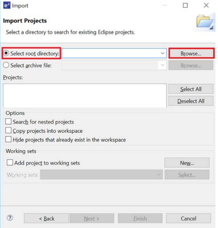
- Select the required project and click Finish.